Glebiys
Junior Member level 2
Hello,
Microcontroller: STM32F303CBT6
What will drive: Dual active bridge (operation based on phase shift between bridges)

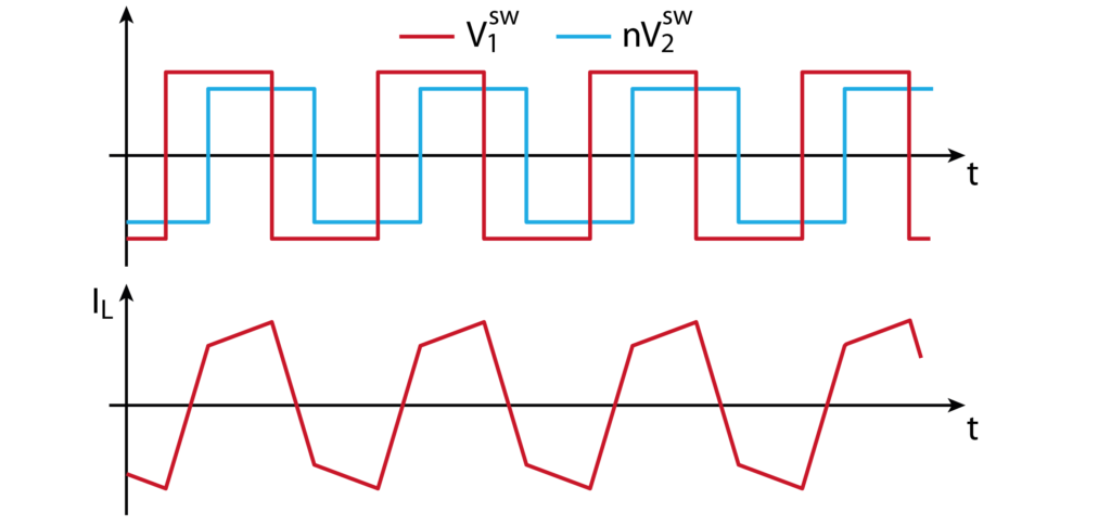
Timers used: TIM1 (primary side), TIM8 (secondary side)
As far as I understand, one timer is set as a Master, the second as a Slave, and between them you can adjust the phase shift.
Questions:
1) How many channels should be used to control one bridge?
A - Use one channel as complementary outputs (eg TIM1_CH1 controls one pair of transistors, TIM1_CH1N controls another pair).
B - For each transistor in the bridge, use its own PWM channel (TIM1_CH1, TIM1_CH2, TIM1_CH3, TIM1_CH4).
С - Use x2 channels per bridge
2) During DAB operation, the phase shift between the bridges may change frequently (control loop). What about changing the phase shift on the fly? Does it require synchronization measures? How difficult is it?
Thank you!
Microcontroller: STM32F303CBT6
What will drive: Dual active bridge (operation based on phase shift between bridges)
Timers used: TIM1 (primary side), TIM8 (secondary side)
As far as I understand, one timer is set as a Master, the second as a Slave, and between them you can adjust the phase shift.
Questions:
1) How many channels should be used to control one bridge?
A - Use one channel as complementary outputs (eg TIM1_CH1 controls one pair of transistors, TIM1_CH1N controls another pair).
B - For each transistor in the bridge, use its own PWM channel (TIM1_CH1, TIM1_CH2, TIM1_CH3, TIM1_CH4).
С - Use x2 channels per bridge
2) During DAB operation, the phase shift between the bridges may change frequently (control loop). What about changing the phase shift on the fly? Does it require synchronization measures? How difficult is it?
Thank you!
Last edited: