Continue to Site

Welcome to EDAboard.com

Welcome to our site! EDAboard.com is an international Electronics Discussion Forum focused on EDA software, circuits, schematics, books, theory, papers, asic, pld, 8051, DSP, Network, RF, Analog Design, PCB, Service Manuals... and a whole lot more! To participate you need to register. Registration is free. Click here to register now.

LED Brightness Control with PWM and Timer

Mtech1

Junior Member level 1
Joined
Mar 18, 2023
Messages
17
Helped
0
Reputation
0
Reaction score
0
Trophy points
1
Activity points
164
Hi,

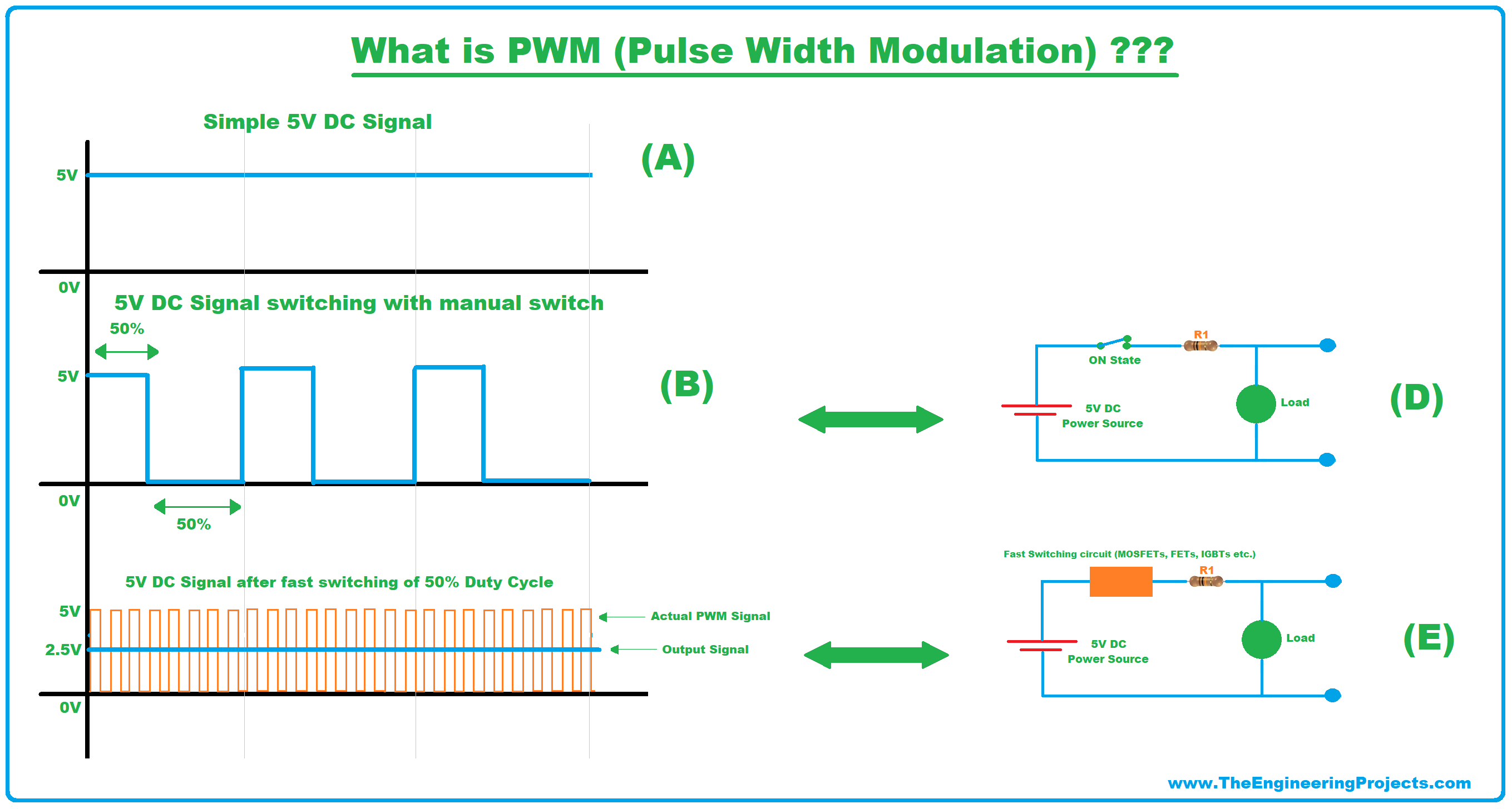
I've come across the concept of controlling LED brightness with PWM (Pulse Width Modulation) using a microcontroller. I looked that adjusting the duty cycle from 0% to 100% is involved in controlling LED brightness. However, I'm looking a clear understanding of the principles behind it, particularly the role of the timer. Researching several sources, I'm still not entirely clear on this.
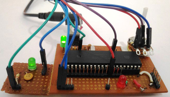


Thank you in advance.
 
Hi,

What is unclear?
Isn´t it obvoius that a LED that 10% of the time is ON is darker than a LED 100% ON?

Maybe you are just confused by the names:
* inside a microcontroller there is a timer/counter/waveform_generation periferal.
It may be use to
* count events (counter)
* to (periodically) raise interrupts, maybe to start ADConversions (with ISR)
* to (periodically) start hardware events, maybe to start ADConversions (without ISR)
* waveform generation (PWM, no interrupt, no ISR needed)
* to capture the timing of an event (capture unit)
* and so on.

Klaus
 
Last edited:
Counter Operation: The counter starts counting from zero. When it reaches the compare value (determined by the desired duty cycle), it toggles the output signal from ON to OFF or vice versa. This process repeats with each cycle of the counter.

Other
Before you can choose PWM, you must define what frequency is required depending on the application. Static (non-moving eyes) and motion pictures can tolerate 25 Hz. LCD's can operate at 50 or 60 Hz minimum. But fast-moving car LED's must operate at much higher frequencies to avoid the stroboscope effect. (Cadillac was the 1st, I've seen to make LED brake lights and have this fault)

In 8 bit uC with 10 bit PWM counters, you must define all the configuration bits with prescaler counters 1, /2, /4, normal or inverted output, which ports etc.


Timers are essentially counters that count from a value, up or down, and when they exceed
a value, reset and repeat the process.

Timers, if you control the length of time a square wave is low, and same for high, this
can be done with timers. PWMs are essentially timers with a compare register. So imagine
a timer counting up (or down) for awhile, and if the low comparator says its counter value
(in the timer) is < some value, the output stays low. Now when the compare value is exceeded
the output goes high. So in effect with a counter and a compare register looking at the counter
value we can control duty cycle of the timer.

1697561954190.png


PWMs are essentially specialized Timers, where one can control the duty cycle and in most
modern versions dual where 2 waveforms have a dead zone between them. Example :

1697562132044.png


Notice how there is a small time between waveforms where both are off or at logic 0.
Use of this for another time.

So back to PWM, so if we change its duty cycle then its load, in your case LED, is on and off
within each period of the waveform. So user sets frequency, then changes the the registers
to control duty cycle. If this is done fast enough, say 120 Hz or faster , the eye has persistence
and does not see the on off switching. But it does see the average brightness change.

Google youtube many videos on basic and advanced Timer/PWM operation.

Regards, Dana.
 
Last edited:
Hi,

What is unclear

Hi,

I've looked the four registers mentioned in the given link:

1. **Caption (CCP1 Control Register):** I understand that this register is used to configure the operating mode of CCP1, which can be set to capture a signal or generate a PWM signal. This makes sense to me.

2. **T2CON (Timer 2 Control Register):** I also understand that T2CON is used for configuring and controlling Timer 2.

However, I'm having trouble unu how the last two registers, **PR2 (Timer 2 Module Period Register)** and **CCPR1L (CCP Register 1 Low)**, work to control the brightness of an LED. Could you please explain their specific role in the context of LED brightness control?

Thank you for your help in clarifying this
 
To control the brightness of an LED using Pulse Width Modulation (PWM) on a microcontroller or microprocessor, you would typically use Timer 2 along with the PR2 and CCPR1L registers. Here's how they work in the context of LED brightness control:
  1. PR2 (Timer 2 Module Period Register): This register determines the PWM signal's frequency. It sets the period for Timer 2, which indirectly affects the PWM signal's frequency. The PWM frequency is calculated using the following formula:
    PWM Frequency = Fosc / (4 * (PR2 + 1) * (TMR2 Prescaler))
    • Fosc is the oscillator frequency of your microcontroller.
    • PR2 is the value you load into the PR2 register.
    • TMR2 Prescaler is the prescaler value for Timer 2 (usually 1, 4, 16, or 64).
      By adjusting the value in the PR2 register, you can change the PWM frequency. Higher PR2 values will result in a lower PWM frequency, and lower PR2 values will lead to a higher PWM frequency.
  2. CCPR1L (CCP Register 1 Low): This register controls the duty cycle of the PWM signal, which directly affects the brightness of an LED. The value you load into CCPR1L determines the ON time of the PWM signal. It should be a value between 0 (fully off) and PR2 (fully on). The duty cycle is calculated using the following formula:
    Duty Cycle = (CCPR1L / (PR2 + 1)) * 100
    • CCPR1L is the value you load into the CCPR1L register.
    • PR2 is the value you loaded into the PR2 register.
      By varying the value in CCPR1L from 0 to PR2, you can control the LED's brightness. A lower value in CCPR1L will result in a shorter ON time and dimmer LED, while a higher value in CCPR1L will result in a longer ON time and a brighter LED.
In summary, PR2 sets the PWM signal's frequency by determining the period of Timer 2, while CCPR1L controls the duty cycle, which determines the LED's brightness. Adjusting these two registers allows you to achieve smooth and precise LED brightness control using PWM.

Ref OpenAI. (2023). ChatGPT (September 25 Version) [Large language model]. https://chat.openai.com/c/c3327827-82c9-4ee6-9e24-6f44278d57ef
 
Perhaps the misunderstanding is how PWM makes the brightness appear to change. The principle relies on persistence of vision and the human eye not being able to react very quickly to changes in light level.
The brightness using PWM is usually nothing or full brightness, there is no real mid-level. What makes the brightness appear to change is how long the LED is at full brightness compared to how long it is off within a fixed time period.

The timer register (set with PR2) is a a repeating interval that sets the cycle period. It is usually fixed and fast enough that the eye can't react to it. You decide the period, any lower than about 25Hz will give noticeable (and irritating) flicker if the LED or the viewer are stationary relative to each other, shorter periods (higher speed) is needed is one or the other moves or you see a strobing effect.

The PWM (CCP) registers set how long within each cycle the output is high and low. A shorter 'on' period makes the LED appear dimmer even though it still emits the full brightness when it is on. By varying the PWM on and off ratio you can make the LED appear to change brightness.

For example, using slowed down times, if the cycle period was one second and the LED was off for the whole time it wouldn't light up at all. If it was on for the whole second it would appear at full brightness all the time. If you turned it off for half a second and on for half a second, the average brightness is half. Now speed it up many times so you can't see the actual flashing and the LED seems to be half brightness. By varying the ratio of on and off times within each cycle you can get as many apparent brightness levels as the PWM register allow.

Brian.
 
For future reference, quick and dirty projects can be done with block programming.

This is mBlock, there are several others on web with various capabilities.

1697572023742.png


Basically you drag and drop function blocks onto design canvas and config. mBlock then converts
block configuration into Arduino code and programs the board, in this case a Nano board.

Other examples of what can be done :

https://www.electro-tech-online.com...roject-involving-a-timer.162287/#post-1411015 __________post #10

The proto :

1697572289692.png


Regards, Dana.
 
You have already got many helpful materials from the answerers. Here is also an easy to understand write-up on PWM. You can take a look.


LaTeX Commands Quick-Menu:

Similar threads

Part and Inventory Search

Welcome to EDABoard.com

Sponsor

Back
Top