delta136
Newbie level 5
Hey all,
I was wondering if you could help me with my homework.
I need to implement a 4-bit multiplier at the gate-level in verilog using AND gates and adders
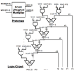
I've drawn the layout, but I'm having trouble translating it to Verilog.
When I instantiate an AND-gate, how do I extract the least significant bit from the AND's output?
for instance, I instantiate an AND gate like so:
// multiplicand = 4'b1011, multiplier = 4'b1110
and(result, multiplicand, {4{multiplier[0]}});
Mathematically, this would be 1011 & 0000 = 0000 <- result
How would I extract the least significant bit at the 0th index and store it at at p[1] or low[1]?
Here's my code, am I on the right track?
Thank you for the help!
- - - Updated - - -
I'm implementing a 4 bit multiplier, but the assignment is to make a 32-bit multiplier. I'm doing it on a small scale to make sure it works before implementing the full 32 bits.
Here's the gate design

I was wondering if you could help me with my homework.
I need to implement a 4-bit multiplier at the gate-level in verilog using AND gates and adders
I've drawn the layout, but I'm having trouble translating it to Verilog.
When I instantiate an AND-gate, how do I extract the least significant bit from the AND's output?
for instance, I instantiate an AND gate like so:
// multiplicand = 4'b1011, multiplier = 4'b1110
and(result, multiplicand, {4{multiplier[0]}});
Mathematically, this would be 1011 & 0000 = 0000 <- result
How would I extract the least significant bit at the 0th index and store it at at p[1] or low[1]?
Here's my code, am I on the right track?
Code:
module unsigned_mult4(output [3:0] high,
		        output [3:0] low,
		        input [3:0] mcnd,
		        input [3:0] mplr);

	wire [3:0] and_result [3:0];
	wire [3:0] adder_result [2:0];
	reg [3:0] carry;
  	reg [7:0] p; // product of multiplication

  	and(and_result[0], mcnd, {4{mplr[0]}});
  	p[0] = and_result[0][0]; // compilation error here. Do I need to use 'assign'?
        and(and_result[1], mcnd, {4{mplr[1]}});
	half_adder ha0(adder_result[0], carry[0], and_result[1], and_result[0]);
        p[1] = adder_result[0][0]; // compilation error here

.
.
.
endmodule
Thank you for the help!
- - - Updated - - -
I'm implementing a 4 bit multiplier, but the assignment is to make a 32-bit multiplier. I'm doing it on a small scale to make sure it works before implementing the full 32 bits.
Here's the gate design

Last edited: