Continue to Site

Welcome to EDAboard.com

Welcome to our site! EDAboard.com is an international Electronics Discussion Forum focused on EDA software, circuits, schematics, books, theory, papers, asic, pld, 8051, DSP, Network, RF, Analog Design, PCB, Service Manuals... and a whole lot more! To participate you need to register. Registration is free. Click here to register now.

Cap & diode in DC environment

Status
Not open for further replies.
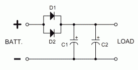
The first schematic will not allow the capacitors to power the load.

By the way, in frigid cold it's conceivable that parts can shift inside a capacitor, either the wires or the paper/wax/chemicals, etc.

This can cause reduced ability to hold a charge, or at worst a short circuited capacitor.

Did you test that the caps can hold a charge in cold temp? Each cap independently?
And that they can provide 12 V to a load of maybe 1000 ohms? (Or based on whatever is your instrument's current draw.)
For several seconds?
 

Just now I had to drive so I cranked her up, after a 5-day standstill and clock didn't reset. Now I'm completely puzzled.
I know just one 10kuF cap is enough because before I disconnected the battery for about 10-15 seconds and the clock didn't reset.

Anyhow, how would a correct shematic look like for 2 caps and 2 diodes?
 

That would be the same as in your second schematic except that a second diode will be in parallel with the first. Like this -

22_1322853874.png
 
Great! Thanx!!!
Gonna try it tomorrow & see what happens
 

Even though I drove yesterday, this morning the clock reset itself again. And the temps are back up again (above freezing point - above 32°F). So I took out caps and diode, and tested the diode: it was OK. So I wired all back again, using the scheme Pjdd posted in post #23, only I've put all three diodes together (2 diodes 45V 8A and one 45V 7.5A) and 3 caps (35V 10000uF each). Put it back in and seems I've wired it OK since the comp thingie had power. We'll see in the next few days what happens...

As for the caps, two of them (identical) have written on them: Rubycon, 35V, (M)105°C (221°F) while the 3rd one is no-name, just 35V and 85°C (185°F, no "m" mark there). I took care to wire all (+) together and all (-) together too. So what's this temp rating? I don't belive they're surposed to BE at that temp to work, that's too high.

I hope for the best - I'll make sure to post back in a few days what's going on now...

One more thing: there's a button on the comp thingie that I can depress at any time, without a key in the lock, that will turn on the display to show date and time for a couple of seconds. THat's how I know the clock didn't reset overnight but rather while cranking. Maybe I should get a stronger battery? THis one is less than a year old and is exactly to the specs (680 cca). Maybe if I get the same size battery but with 780 cca would help? She cranks very well, no that almost-to-die slow cranking but lively crank and she fires right up. Dunno... Also, it's not a bad soldering point or bad connection since our roads are almost off-road rated and there's a lot of shaking all the way so if it was that, the clock would reset even while driving, which never ever happened. On the other hand, when I bought the Jeep (used), the battery was old & weak so if I didn't crank her every 2 days the 3rd day the batt would be too weak to crank. And in that period, until I got the new battery, the clock would reset every time, regularly. Changed the batt and it was all well, until the colder days came and temps dropped to 0°C and below (20-30°F) and below.

I wanted to open the comp and take pics of the chips, but I couldn't. It's too many brittle plastic holders that would break just by looking at them.
 

I will not suggest you to open the comp box. If you want a look inside it, better get a wiring schematic from the manufacturer or try here on NET to find out the model numbered diagram. Here is the guide in schematic type symbols.
Batt.jpg
Hope it helps and your problem gets solved.
 
Last edited:

It's all a bit puzzling. It sometimes happens that someone brings a problem to a forum and it sounds like something that someone with good experience would be able to solve without too much trouble if that someone were on the spot, but not by remote guidance.

In some such cases, the person with the problem does a poor job of relaying information and of following the more experienced person's guidance and makes things more difficult than they would otherwise be. Happily, this is not one of those cases. You've done an excellent job in that respect.

Re the temperature markings on the caps, those are just maximum ratings that should not be exceeded. And I have a feeling that it's not simply a matter of getting a sexier battery. It would help if you could measure the voltage at certain points and the current drawn by the load in question under different conditions - when the engine is off, when the ignition switch is on but before cranking the engine, and while cranking.
 
It would help if you could measure the voltage at certain points and the current drawn by the load in question under different conditions - when the engine is off, when the ignition switch is on but before cranking the engine, and while cranking.
Not even that - I'd suggest putting something across that board computer's DC input that gives a fast-responding, visual indication of the voltage. Say, a small bulb like you'd use on a bicycle (but rated for 12V). That way if you start the car, you can watch how its brightness responds to the changing battery voltage / diode / capacitor circuit. A LED might be less suitable for this given its current / brightness characteristics (but it would change brightness quicker than a glow bulb).

That wouldn't give you accurate numbers, but a nevertheless a good view of what's actually happening in terms of voltage drop (and how effective diode / capacitor circuit is in countering that).
 
Thanx, Pjdd

RetroTechie, that's a good idea. I'll get a LED cos I can put it in a dark spot where I can still see it, and see what happens....
 

So, it's been 5 days since I didn't drive. Went yesterday, and all was well! Clock & date didn't reset, obviously the caps held good. Temps outside were from some 32F in the coldest part of the morning, up to 55-60F in the warmest part of the day, so no too much trouble but nevertheless, the sstem held well.

So, thanx to y'all who chipped in, this problem got solved (knock wood, ey).

THANX!!!
 

Nice of you to take the time to report back. A lot of people don't bother unless they are regulars in the concerned forum or newsgroup anyway. Be nice to hear again how it goes after, say a month.
 
I needed help and ppl here helped me out. Saying "thanx, it's OK now" is the least I can do. And pulite, too ;)

I will be reporting again after a month or so, of course!
 

Well... Same thing again. After 5 days no reset. That was saturday. Today, monday, it reset again. I don't know what to do, I don't have any more ideas. I belive 30000uF combined with three diodes with a total of 23.5 amperes would be an overkill for such a thing, but it's obviously not. I am thinking of throwing the darn thing out and be done with it...
It's just unbelivable that the techs at Chrysler would do such a lousy job. Maybe it's the computer thingie that's fried altogether? But aside from this resetting problem it works perfectly. Maybe its own caps are too old and need replacing? Dunno...
 

I went back to your initial post. You said it "resets when cranking". Do you mean that the correct time and date are displayed when you turn the key on, but not after you turn the engine over? Or, has it lost its memory by the time you turn the key on? Maybe we haven't been asking ourselves the right question.
 

When cranking: if I turn the key to on, clock is ok. Then I crank, the engine comes on, and the clock resets.
 

Try connecting your voltmeter to the capacitors, and monitor the voltage while cranking. If it doesn't drop appreciably, and the clock still resets, the memory power isn't the problem. If it does drop, use a rechargeable battery in place of the capacitors.
 

Voltmeter connects in parallel with caps? Or in series?
 

In parallel.
 

It could just be a bad ground. try connecting a wire between the - side of the capacitors and the radio(?) chassis
 

I just checked the wiring info - the darn thing has 3 GND pins, all 3 going to the same splice. Which is, of course, in the engine compartment, well covered & hidden. So I'm gonna have to manually override the GND for all 3 pins to a known good GND location (like a nearby bolt going through the chassy, that ought to do it). Oh joy :/
 

Status
Not open for further replies.

Similar threads

Part and Inventory Search

Welcome to EDABoard.com

Sponsor

Back
Top