Continue to Site

Welcome to EDAboard.com

Welcome to our site! EDAboard.com is an international Electronics Discussion Forum focused on EDA software, circuits, schematics, books, theory, papers, asic, pld, 8051, DSP, Network, RF, Analog Design, PCB, Service Manuals... and a whole lot more! To participate you need to register. Registration is free. Click here to register now.

Frequency counter design

Status
Not open for further replies.

rahulloveselectronics

Junior Member level 1
Joined
Feb 8, 2008
Messages
15
Helped
0
Reputation
0
Reaction score
0
Trophy points
1,281
Activity points
1,403
Hello,

I need to design a frequency counter, where my input frequency will be less than 3Mhz (square wave input). I have seen many microcontroller based implementation. But this frequency counter is part of my ASIC design, so I wanted to design it using CMOS. Can someone help me out.

Thanks in advance!
 

Best that I will recommand you to use either a FPGA or CPLD....with CMOS you need to think many things about sampling rate and dealy issues...if the COMS differ in characterstics then your problem is more complicated....in FPGA or CPLD it will be very simple to implement...also what you can do it first code in FPGA or CPLD get the Logic gates and memory element circuit with clock in FPGA..... can be directly transfered in CMOS...by making logic component in CMOS....but still the delay and sampling will be critical as you are planning to have off chip components....

Good Luck
 

Hi..thanks for your reply....

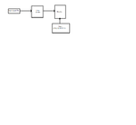
Can you please see if the below mentioned implementation is fine. frequency counter.png

the lowest frequency change to be detected is 500hz and the highest being 3Mhz signal. Now, that corresponds to 6000 (3Mhz / 500) states. Hence a 13 bit (2^13= 8192) counter will be used to count at each input rise edge. A timer would produce a 2ms gating signal (2ms = min frequency of 500 hz) which will be connected as a control signal to a register. The register which will read the value from the counter once the gating signal (2ms) is applied. This corresponds to N pulses / 2 ms and thus the frequency would be N/2 Khz.

Please let me know your inputs.

Thanks
 

I just want to understand that the range of 500hz to 3Mhz or 500hz integral multiple up t0 3 Mhz.....as per my understanding .....if I read your code i feel that you want 500Hz intergral multiple sampling.....generally frequecy measurment is done using counting number of pulses per fixed amount of time .....with the no of pulse for the reference clock....I mean you need to have a counter for some thing like 10Mhz signal....at least 6Mhz so to measure 3 Mhz frequency accuratly based on Nyquist.....then you keep a counter for input measure the pules or low to high transistions for say one mili sec.... so if you are using a sysnchronous counter operating at Clock frequecy let say 10Mhz then .....you will count for 3Mhz almost 3333.3 pulses / transistion ....similarly you will count 10000 pusles for 10Mhz.....the ratio of them gives the frequecy of the measurement ..... I am not able to understand how did u come on number of 6000 and 13 bit counter idea..... are u looking integral multiple of 500Hz then it makes some sense....however I am not very clear about your idea of gate signal.....
 

yes the frequency is changing in steps of 500Hz. Gating signal was just to denote the time period for which the counter will be counting (in your case: 1ms).
 

To make your circuit to work i think then you need to think for the clock that you used for counter...look at this way....if you are operting the counter at 500hz frequecy and the input singal is 1500Hz let say....you will miss the 2 pules at least before rising edge of clock comes so detection will be possible maximum for 500Hz if you have synchroized both clock and input period....but you will not able to measure 3Mhz in any case ...as per my understanding you need to have at least counter clock of 6Mhz and the getting signal of of even 6Mhz...should work in your case...

Good Luck
 

But this frequency counter is part of my ASIC design, so I wanted to design it using CMOS.
What do you mean exactly with "my ASIC design?" :?: (ASIC normally means: an IC specifically designed for an application, this does NOT include "programmable chip that does what I program into it" like microcontroller, CPLD, FPGA etc).

In general, you're comparing input clock with a reference clock signal, and therefore reference clock must not only be accurate (small variation in frequency), but also very stable (low jitter, read: small variation in exact duration of individual clock periods).

This jitter would be bigger problem when input clock frequency >> reference clock, and for that reason I'd pick a high frequency reference clock (and obtain gate signal as reference clock divided by a high number), so that you only have to worry about the reference clock's frequency stability. Nyquist isn't relevant in this context since you're not (that is: shouldn't be) using the reference clock directly to 'sample' the input clock signal.

So even if you're measuring 3 MHz max it wouldn't hurt to pick faster logic with say, 10-50 MHz reference clock (only a small part of the logic needs to be as fast as the reference clock). And resolution would depend on # of bits (or digits) in the counter, not on what you use as reference clock.

the lowest frequency change to be detected is 500hz and the highest being 3Mhz signal. Now, that corresponds to 6000 (3Mhz / 500) states. Hence a 13 bit (2^13= 8192) counter
Makes sense, but I wonder how you plan to read counter value - a row of LEDs? Some external device? Display built into counter would seem more convenient, in that case it might be more useful to have a decimal counter (=groups of 4 bits representing digits 0-9 in the count value).

Btw why is this thread in "Analog Circuit Design" ??
 
Last edited:
What do you mean exactly with "my ASIC design?" :?: (ASIC normally means: an IC specifically designed for an application, this does NOT include "programmable chip that does what I program into it" like microcontroller, CPLD, FPGA etc).

I have some analog circuits and along with this frequency counter for my application, which I wanted to implement in an IC.

This jitter would be bigger problem when input clock frequency >> reference clock, and for that reason I'd pick a high frequency reference clock (and obtain gate signal as reference clock divided by a high number), so that you only have to worry about the reference clock's frequency stability. Nyquist isn't relevant in this context since you're not (that is: shouldn't be) using the reference clock directly to 'sample' the input clock signal.

So if I consider this ref clock freq condition, would this suffice for implementing a frequency counter?

Makes sense, but I wonder how you plan to read counter value - a row of LEDs? Some external device? Display built into counter would seem more convenient, in that case it might be more useful to have a decimal counter (=groups of 4 bits representing digits 0-9 in the count value).

Yes, I was thinking of interfacing the output to some LEDs. But frankly, vnt thought much about the external interfacing.

Btw why is this thread in "Analog Circuit Design" ??

Sorry for that, I used to make use of this forum usually. So, didn check that before posting it here.
 

Given that your signal is cmos compatible level (eg. no level shifting required), then I'd make some clock source using for example CD4521 which would give frequency of let's say 0.5Hz Then the clock signal is high for 1 second and low for another 1 second. I'd AND this signal with input signal which would give effect of gating input signal with clock signal. Then input that to a counter (say few units of daisy-chained 74193) which is being reset every rising edge of clock signal. Use some latch to remember value of the counter on falling edge of clock (might need an inverter). The latch contains you frequency count.

This is just a general idea, actual implementation would have to be simulated :) or experimented upon.
 

Status
Not open for further replies.

Similar threads

Part and Inventory Search

Welcome to EDABoard.com

Sponsor

Back
Top