Continue to Site

Welcome to EDAboard.com

Welcome to our site! EDAboard.com is an international Electronics Discussion Forum focused on EDA software, circuits, schematics, books, theory, papers, asic, pld, 8051, DSP, Network, RF, Analog Design, PCB, Service Manuals... and a whole lot more! To participate you need to register. Registration is free. Click here to register now.

[SOLVED] Shielding property of cascode technique, why? Basic Question

Status
Not open for further replies.

palmeiras

Full Member level 6
Joined
Feb 22, 2010
Messages
375
Helped
61
Reputation
122
Reaction score
50
Trophy points
1,308
Location
South America
Activity points
4,199
Hi everyone,

Could someone help me with the following doubt?

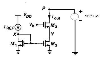
I woul like to understand what is the origin of the “Shielding Property” of the cascode techinque (Device M3) in the current source shown in figure 1. The Shielding property is expected to increase the PSRR.

Do you agree with my following first explanation, composed by itens a) and b)?
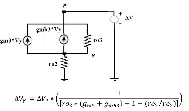
a) When adding M3, there is “a voltage divider” formed by M3 and M2, and therefore, only a fraction of ΔV is transferred to node Y. Therefore, the VDS voltage of M2 is slightly changed, and the channel length modulation effect is reduced. Therefore, the advantage of cascode technique comes from the “voltage division” that is configured.

b) Now if I can consider this “voltage division”, M3 should have higher output resistance than M2 in order to have maximum rejection of ΔV.

If you don’t agree with above explanation, what is the best way to understand the PSRR improvement generated by the cascode technique?

Thank you very much,
Best regards.

27_1298489678.jpg
 

Hello,

When you consider a common gate circuit, you look into a low impedance (1/gm) parallel with a "resistor" 1/yo (output resistance between drain and source).

1/gm has a low value, 1/yo has a high value.

When you look to your circuit 1/gm (M3) is connected to Vb (so AC ground), this makes node M3 source a low impedance node. So because of the 1/yo (M3), 1/gm (M3) voltage division, you will only see a small part of deltaV (M3 drain) at M3 source (= M2 drain).

This small portion of deltaV that appears at M2 drain, will result in small variation of Idrain (M2). As for DC: Id M2 = Id M3, the cascode transistor will reduce deltaV/deltaI (for M3).

It is not required that the output impedance of M3 alone (1/yo in common source) must be higher then output impedance for M2. If 1/yo (M3) decreases, but gm increases (so 1/gm decreases also), the voltage division will not change, hence the output impedance of your cascode circuit.
 
Last edited:
Over some portion of the range, M3 "pins" the drain of M2
to Vb-VTeff. To the extent that M2 VDS is an element of
PSRR, PSRR will be improved.

This falls apart at the voltage extremes, such as when
M3 VDS collapses to the point that Y voltage begins to
follow. It also can fail when ID(M2) desired is less than
the leakage in M3.

Cascodes work very well under certain conditions. The
cost is headroom, real estate and addition of other
noise / error pathways. For example, if Vb were prone
to follow VDD to any significant degree (such as HF
supply noise coming through whatever biases the Vb
reference) your PSRR might see it - M3 is a HF common
source amplifier with M2 Cdd as a peaking cap and Vb
as its input. And so on.

I've seen cascodes used for high DC gain, amplify device
noise badly - current noise on M2 becomes voltage noise
at M3 drain, Inoise*Zout. Make Zout -too- good and you
may be surprised at what your ideal-DC amplifier gets up
to in-the-moment.
 
Hi WimRFP,

Thank you for your replay.
The beginning of your explanation is exactly what I thought when I wrote this topic.
However, I did not understand your last sentence: “The voltage division is not change if we chance the output resistance and gm of M3”.

Please, could you explain your point of view?

For me, the impedance of M3 (1/gm and ro) and the impedance of M2 are separated things. So, if you change one of these resistances, the voltage division will be changed. When W/L is increased for M3, the output resistance of M3 is decrease, and gm is increase. Therefore, the output resistance of M3 is decreased. Am I right or not?!

Thank you.

Hi dick,

Thanks too!

1) Do you think that the shielding property of cascade techniques is analogous to a “voltage division” and therefore, the output resistance of M2 must be low compared to M3?
2) By the way, What do you mean with “M2 CDD?”.

Regards.
 

The output impedance seen into the cascode is gm3ro2ro3.
Increasing any of the impedances and having a increasing gm3 will increase the cascode output impedance.
A more intuitive explanation is that any attempt to increase Id3 will increase vgs3, which will "push" node Y down and hence clamp vds2. With vds2 clamped, and vgs2 remaining constant, Id2 will not change. It is a form of negative feedback.
 
Hello.

When you do the math, you will find the output impedance for the cascode as:

(DeltaV/DeltaI) = 1/yo2 + 1/yo3 + (1/yo2)*(1/yo3)*Gm3

the numbers correspond to M2 and M3.
Normally spoken, you can ignore the first two terms. This reveals the influence of the mosfet properties.

I checked it with a simulation with good agreement

Of course if you will increase frequency, you also should take into account capacitances and gate resistance and the formulas become significantly more complex.
 
Hi guys, thanks for your replies.

Checkmate, one key point of our discussion is the feedback that you explain. Thanks.

However, I think that:

Higher r03, smaller will be the transfer of a signal from node P toward the node Y. (Please, take a look in figure 2 - small signal model, and the transfer function equation).
Therefore, I believe that higher the r3 higher PSRR.


Hello Palmeiras,

Correct, increasing ro3 (1/yo3 in my formula) increases the schielding, hence gives better PSRR. The sad thing is when increase in ro results in inverse proportional reduction of Gm3, it will not help you much. But I assume you know your process better then me.

Good luck with further designing your circuit,


Wim
 
  • Like
Reactions: palmeiras

    palmeiras

    Points: 2
    Helpful Answer Positive Rating
    V

    Points: 2
    Helpful Answer Positive Rating
Status
Not open for further replies.

Part and Inventory Search

Welcome to EDABoard.com

Sponsor

Back
Top