Continue to Site

Welcome to EDAboard.com

Welcome to our site! EDAboard.com is an international Electronics Discussion Forum focused on EDA software, circuits, schematics, books, theory, papers, asic, pld, 8051, DSP, Network, RF, Analog Design, PCB, Service Manuals... and a whole lot more! To participate you need to register. Registration is free. Click here to register now.

[SOLVED] TR Saturation for Cascode Amplifier

Status
Not open for further replies.

movinghoon96

Junior Member level 1
Joined
Jan 27, 2023
Messages
19
Helped
0
Reputation
0
Reaction score
0
Trophy points
1
Activity points
163
Hello, I'm trying to design Cascode Amplifier. I've spent over 1 week reading textbook to fix this, but couldn't solve it yet. Really need some advice to breakthrough.
MOSFETs are not in Saturation Region, I'd like to know why and how to fix it.
Suggesting Textbook, Article is all OK. Need any clue for it.

[Before Enter]
I've already designed simple 2-stage 5OTA - 1 stage : 3uA 2 stage : 100uA
according to slew rate, frequency. it worked fine.

so I choosed 3uA for 1-Stage Cascode Amplifier. and Bias circuit seems working well.

[MOSFET Info]
Process Minimum (W/L) = almost (0.5um/0.5um)

1) NMOS (Vth0 = 0.42)
(W/L) = (2.5um/2um), Id = 1.5uA @ Vgs = 0.52V & Vds = 0.15V
gm = 20uS, ro = 914kohm

2) PMOS (Vth0 = -0.67)
(W/L) = (15um/2um), Id = 1.53uA @ Vgs = -0.77 & Vds = 0.15V
gm = 20uS, ro = 1.6Mohm

Image2.png

KakaoTalk_20231220_162001699.jpg


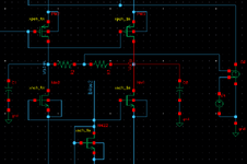
① Cascode is not in saturation
I set Input Vi+,Vi- = 1.25V according to hand calculation.
And I got AC Gain = -15dB for 10Hz.
I guess it because my TR is not in saturation.

② Bias Voltage for NM0,1 is not calculated
I found Diode-Connected Device is recommended for level-shifter, requiring current lower than 'real' branches.
But how low? Couldnt find meaningful answer on Sedra&Smith, Razavi's textbook.

Image1.png
 

A fully differential opamp needs a Common Mode Feedback Circuit (CMFB).
first of all, thank you for replying.

yes, I've read fully differential needs CMFB for mismatch. really need for 'real' IC
I was going to apply CMFB after some improvement (Folded-cascode, Gain-boosted...etc) because I thought simulator doesn't have mismatches.
: 10:03 on this video, it doesn't have CMFB but its output has 56dB.
so I thought there is no problem to apply it. Maybe my bias circuit has some problem?
 

first of all, thank you for replying.

yes, I've read fully differential needs CMFB for mismatch. really need for 'real' IC
I was going to apply CMFB after some improvement (Folded-cascode, Gain-boosted...etc) because I thought simulator doesn't have mismatches.

Just check the Ibias1 and Ibias3 in your bias circuit. Are they in the exact proportion that you expect them to be in? They are not cascoded either.

In the video they have not used any bias circuit but seem to have used very absurdly specific sizes to balance the circuit. 1.799u and what not. It is not a particularly great design.

Put in some ideal CMFB using a vcvs or something.
Thank you. I'll

i) reinforce bias with cascode block
ii) applying CMFB

i have never thought cmfb would be problem
 

If you see the structure of your opamp, basically it is opposing current sources.

You have Ibias2 and PM0 and PM1 sourcing current and NM8 sinking it at the bottom.

Just imagine what would happen to the center voltage if a current source and a current sink are in series and their values are not equal
Hello, I have applied some points that you suggested.

1) Bias Block
Bias.PNG

i) added same (W/L) cascode to Ibias1, Ibias3

2) Main Block
View attachment Image2.png
i) CMFB
R2 = R3 = 100Mohm, V4(VREF) = 1.325V, E0(vcvs) = 100
ii) All TR body to its source
Realized neglecting body effect gamma needed -> 10dB increased
In real circuit, i can resize (W/L) to adjust Vgs, but now body-source for convenience.


3) Result
i) only input TR isn't going saturation
guess it makes gain worse.
ii) CMFB working fine
Vocm = 1.34V : similar with V4(Vref) of CMFB, when Vi+=Vi-=1.25V
iii) Gain is still low
it now has 9.8dB - way better than before, but it is still low and phase is awful.

5.PNG


※ this is OPAMP I made with other process(but minimum (W/L) is similar)

4.PNG
 

Attachments

  • Main.PNG
    Main.PNG
    21.9 KB · Views: 43

Hello, I have applied some points that you suggested.

1) Bias Block
View attachment 187153
i) added same (W/L) cascode to Ibias1, Ibias3

2) Main Block
View attachment 187155
i) CMFB
R2 = R3 = 100Mohm, V4(VREF) = 1.325V, E0(vcvs) = 100
ii) All TR body to its source
Realized neglecting body effect gamma needed -> 10dB increased
In real circuit, i can resize (W/L) to adjust Vgs, but now body-source for convenience.


3) Result
i) only input TR isn't going saturation
guess it makes gain worse.
ii) CMFB working fine
Vocm = 1.34V : similar with V4(Vref) of CMFB, when Vi+=Vi-=1.25V
iii) Gain is still low
it now has 9.8dB - way better than before, but it is still low and phase is awful.

View attachment 187162

※ this is OPAMP I made with other process(but minimum (W/L) is similar)

View attachment 187160


++++++
all TR into saturation by adding additional Diode-Connected Ibias2! and decreaseing Width!
Now re-calculating is required but i think i found way to solve!
thank you for cmfb it was helpful!
 

Status
Not open for further replies.

Part and Inventory Search

Welcome to EDABoard.com

Sponsor

Back
Top