Continue to Site

Welcome to EDAboard.com

Welcome to our site! EDAboard.com is an international Electronics Discussion Forum focused on EDA software, circuits, schematics, books, theory, papers, asic, pld, 8051, DSP, Network, RF, Analog Design, PCB, Service Manuals... and a whole lot more! To participate you need to register. Registration is free. Click here to register now.

IS this a good idea? Measuring AC current.

Status
Not open for further replies.

Sajjadkhan

Full Member level 5
Joined
Sep 25, 2010
Messages
307
Helped
17
Reputation
34
Reaction score
16
Trophy points
1,298
Location
Rawalpindi,Pakistan
Activity points
4,199
check this out. Is it good idea to meausre AC current. I did a simulation and it went fine and there was a linear change with respect to input.


Something like that can work, but it works as a voltage transformer so the diodes cause nonlinearity on the output. Using a standard current transformer doesn't have this problem. Also easier to construct than what you posted (effectively no primary winding).
 
Something like that can work, but it works as a voltage transformer so the diodes cause nonlinearity on the output. Using a standard current transformer doesn't have this problem. Also easier to construct than what you posted (effectively no primary winding).

can you explain how diode causes nonlinearity, because its forward voltage will be fixed and the output will fed to ADC which is a very small load and constant. Though i admit that it the load is variable and increases then it draws more current and forward diode voltage changes non-linearly as current increases.
 

The non-linearity comes from the forward bias voltage of the diodes. They wont conduct until youve exceeded the forward bias this will effect readings when you are measuring small currents. There are plenty of application notes on how to use an op amp as a fullwave rectifier that does away with this limitation
 

It all depends on the application, first of all the 1K load will cause more diode volt drop then might be required. I think your AC current is in the order of 10 A, so if you are just interested in measuring 10A +- 5A, this circuit would do (+-2%). Also if you use a ready made mains transformer (230 ->6V?), it will have the required insulation built into it. the higher output voltage would allow you to have a secondary voltage of 40V RMS, allowing you to use a high value series resistor, giving better linearity.
Frank
 

The non-linearity comes from the forward bias voltage of the diodes. They wont conduct until youve exceeded the forward bias this will effect readings when you are measuring small currents. There are plenty of application notes on how to use an op amp as a fullwave rectifier that does away with this limitation

In simple terms that is called offset. and if current is very small and constant then that offset mearly chnages and it can be handled in software.
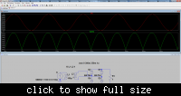
---------- Post added at 14:48 ---------- Previous post was at 14:48 ----------

Any ways then what will be an accurate system of measuring AC current? Current transformers or Hall effect sensors? accuracy required up to 0.1 amps and max current will be up to 10 Amps.
 

In simple terms that is called offset. and if current is very small and constant then that offset mearly chnages and it can be handled in software.
In measurement technique, its called a systematic error. As it also depends on temperature and current waveform, it can't be easily cancelled in software.


To analyze the operation of your original circuit more thoroughly, you should vary load resistance in a parameterized analysis and record the current versus recitifier output characteristic. Apart from all guesses, you should be able to determine linearity and current accuracy yourself.

You didn't tell the transformer voltage ratio, so we are unable to calculated it.

The 0.1 ohm shunt is involving not less than 10 W power dissipation at 10 A load current. In so far, it's not a good idea, I presume. A regular current transformer should cause considerable lower losses at 10 A.

In a limited application range, a really low resistance (mohm range) shunt can make sense. It's often used for cheap energy meters, particularly with measurement circuits without isolation from mains power. It could work with a small transformer as well, but a true current transformer with secondary shunt promises better performance if isolation is required.

Generally, current transformer is the preferred method for AC currents. Hall sensors come into play for DC currents.
 
Last edited:

In simple terms that is called offset. and if current is very small and constant then that offset mearly chnages and it can be handled in software.

No, it's not just an offset, the diodes will not allow any signal to come out which is not high enough to forward bias them. Any signal content between -1.2V and +1.2V simply won't show up on the output, and that information is lost and can't be recovered.

Do you need to actually rectify the output signal? It can be done with a current transformer without introducing significant distortion, but generally the current transformer will need to have very high inductance, especially if it needs to operate at low frequencies.

yes you are right, that info cant be recovered. In that case dont you think the rectifier you and i used also contributes to the error? i think so. so then i think i shoud use a summing amplifier with two inputs. one would be having a DC offset say 5V and if say my CT gives 10V peak to peak then the swing will be from 0 to 10V or simply no need of offset just half positive cycle will do the job, the average would be done in controller, right?
 

yes you are right, that info cant be recovered. In that case dont you think the rectifier you and i used also contributes to the error? i think so.
No, because in my case the output of the transformer is a more like a current source than a voltage source, and the burden resistor is on the output of the rectifier, so it doesn't distort the output voltage. You can see the waveforms give a good linear measurement (1A of current through a 1:100 CT, with a 1 ohm burden resistor gives 10mV output).
 

The CT + rectifier circuit has a residual nonlinearity caused by the transformer main inductance, but surely lower than the primary shunt variant.
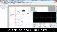
 

The CT + rectifier circuit has a residual nonlinearity caused by the transformer main inductance, but surely lower than the primary shunt variant.

adding a resistor will give very good linearity to ct and full wave op amp is just excellent in the +/- 10u micro volts range with instrumental amps .
if fluke uses it then its ok. and i have a fluke diagram.
 

The CT + rectifier circuit has a residual nonlinearity caused by the transformer main inductance, but surely lower than the primary shunt variant.
Correct, it will have some finite amount of distortion, especially at low signal amplitudes. For lower distortion, the CT can be connected directly to the burden resistor, and then a precision active rectifier can be used. Best of all would probably be a transimpedance amplifier instead of a burden resistor.
 

"transimpedance amplifier instead of a burden resistor. " its good but the option is based on the idea of virtual gnd of op amp.
its not really shorted to gnd or zero Independence... it will work for small signal micro amps not for amps. and passing 230v and 10-20amps thru rf ...brrr gives me the shivers. and thus add other problems like every thing should be isolated
http://www.ecircuitcenter.com/circuits/opitov/opitov.htm
 

The answer depends on CT windings ratio. 1000:1 isn't unusual for small CTs and would still work for 10 Arms with an OP I/V converter, but at a low crest factor. You also need to protect the OP against current surges, e.g. by antiparallel diodes.

So you'll end up with a passive shunt in many cases.
 
Well i read there were a lot of problems with ct but it depends on saj what is his needs for resolution accuracy sudden changes or surge current etc etc..
but if he wants to check out how much his tv or hair dryer is taking its enough.
i would buy one for 10$ and sell the rest or give them as a birthday present to my other electronics hobby friends .
https://www.alibaba.com/showroom/dc-digital-amp-meter.html
 

Actually i wanted to build a pannel which would be installed in my lab before the switch board, displaying esential readings like current, voltage, temperature, PIR sensor for auto light on/ofnover and under volatage protection.... any other features you suggest that would be necessary?

OK, in my opinion if i use a precision resistor and do not isolate my circuit then apart from saftey it would be more accurate, any thoughts?

0.1 ohms can be changed to 0.01ohms and lm358 can be replaced by instrumental op-amp. rest i think would be simply putting a cap to hold the charge and connect a transistor to that cap if cap is large so to trigger the base of transistor to discharge the cap before taking a new reading.


1)What cap where ?
2)pre..resis.. will work but i would not "apart from safety" do it at any cost especially if yu addind more options to that panel meter .
3) i advice to make some change in circuit and leave the grd sign or ac mains grd....and use return sign for isolated supply, remember if anybody else would copy your circuit.. *** knows what will happen.. try to be precise for future generation.
good luck

current measure.JPG
 
This appears to be a standard CT appln. Your simulation uses an ideal transformer. In a real transformer the following two factors will have to be considered: (a) Magnetizing current caused by the inductance as seen from the primary. This can be modelled as an equivalent inductance in parallel with the primary. (b) Non-linearity of core. If you try to design with an air-core the number of turns will be prohibitive at 50Hz (your target freq). If you use an iron core, the range will be very limited. Once you actually try to calculate the turns you will see the nature of the problem.

I once tried to build a current transformer with EI laminations of an old power transofrmer (50Hz). Even tho I measured the linearity beforehand and had a lookup table when displaying, the accuracy and precision esp. at low currents was unacceptable.

DOnt be misled by various pundits pointing out problems with the rectifier. These are the unimportant details that can be worked around, esp. at 50Hz.

Dirty little secret: Most engineers are ignorant of basic magnetism fundas.

vkj.
 

Status
Not open for further replies.

Similar threads

Part and Inventory Search

Welcome to EDABoard.com

Sponsor

Back
Top