neazoi
Advanced Member level 6
Will a DDS generate harmonics?
Lower, higher, how many?
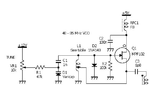
I design a good spectral purity oscillator and I would like to make rought comparisons to a dds http://neazoi.com/singlespanosc/index.htm
Lower, higher, how many?
I design a good spectral purity oscillator and I would like to make rought comparisons to a dds http://neazoi.com/singlespanosc/index.htm
")