Continue to Site

Welcome to EDAboard.com

Welcome to our site! EDAboard.com is an international Electronics Discussion Forum focused on EDA software, circuits, schematics, books, theory, papers, asic, pld, 8051, DSP, Network, RF, Analog Design, PCB, Service Manuals... and a whole lot more! To participate you need to register. Registration is free. Click here to register now.

This has become my biggest doubt of my life...........?

Status
Not open for further replies.
I thought it to be really obvious. Connect A/C (rotor) to ground (they are already internally
connected, can't you see it?!) and B to the "hot" node.
 
FvM said:
I thought it to be really obvious. Connect A/C (rotor) to ground (they are already internally
connected, can't you see it?!) and B to the "hot" node.
u said there will be two terminals in a trimmer...but if A and C are grounded......how will there be two terminals
 

Simple check:

Use an ohm meter to see which two pins are joined together. Use both pins as one connection in the circuit so you minimize the inductance of the pins as much as possible. Also measure the resistance from the adjustment screw to the pins to see which is connected, this is the side to connect to ground. The reason is simple, if you use a metal blade screwdriver and it connects to the top of the tuned circuit (the C3 side) it will add inductance and capacitance to surrounding objects and shift the frequency. On the other hand, if the adjustment slot is grounded all you are doing is touching the screwdriver blade to ground and the effect will be much reduced.

I have a box of these variable capacitors in front of me at the moment and on all of them, the two opposite pins are visibly joined together under the capacitor and also connected to the screw slot so these would be your ground connections. The middle pin is captive in a plastic slot and goes to the fixed capacitor vanes, this is the one at the top in your schematic.

Incidentally, try to get hold of a special 'trimming tool' screwdriver to adjust these capacitors. It's a plastic rod with just a small (3mm x 3mm) metal tip set into it end. These have much less effect on the tuning when you move them close to the tuned circuit components than a metal screwdriver.

Brian.
 

even i have a trimmer in front of me..as u said the two pins as i mentioned A and C are connected together....so these A and C cant be the two terminals of the capacitor right
 

Perhaps I don't understand the question. If one terminal of a capacitor is grounded, isn't it still a terminal?
If one electrical terminal uses two pins, isn't it still one terminal?
 

Use both A and C as the ground side. B goes to the top of the tuned circuit.

Aside from being electrically better to use both pins as ground, with three pins it will be mechanically more stable.

Hey - I just passed the 1,000 post point - I'm now an "Advanced Level 4" member !

Brian.
 
so the pin B goes to the top of the tuned circuit..
and the A and C pins are grounded..
what happens wen we are using a variable cap in this situation
like this one
44_1282677795.gif


will A and C(which are connected together) becomes one terminal and the B( middle pin is captive in a plastic slot) will be another terminal..right and by turning the screw of the trimmer ,the capacitance can be varied..

Added after 2 minutes:

congrats for u hav passed 1000posts

Added after 17 minutes:

AND DOES A TRIMMER NEED A GROUND CONNECTION TO VARY CAPACITANCE AS VARIABLE RESISTORS USE GROUND CONNECTION TO VARY RESISTANCE....?
 

AND DOES A TRIMMER NEED A GROUND CONNECTION TO VARY CAPACITANCE AS VARIABLE RESISTORS USE GROUND CONNECTION TO VARY RESISTANCE....?
They do neither. A variable capacitor is just a capacitor. You can put it in your previous oscillator circuit with
both terminals "hot". But then you have the problem of detuning the circuit while touching the varcap
with a screwdriver. Or you need plastic/ceramic screwdrivers to reduce this effect. That's why I said,
connect the rotor terminal to ground if ever possible. Fortunately, it's possible with the present circuit.
 
i didn't get the meaning of HOT..??
thank u for clearing my doubt on ground connection in trimmers..
till now i thought that there will be ground connection in a trimmer to vary capacitance as in variable resistor...
thank u FvM


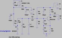
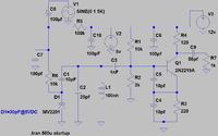
here i have made graphical representation of the variable capacitor In C2 A AND C(WHICH ARE INTERNALLY CONNECTED)ARE GROUNDED AND B PIN IS TOWARDS THE OSCILLATOR UPPER SIDE..
and in C3 both A,C and B are used.....
but C3 faces change of capacitance while tuning with steel screw driver...because none of it terminals are grounded....if the rotor(a and c) are grounded ,then this effect would be reduced ..
DO U THINK MY UNDERSTANDING IS CORRECT NOW..?


Quite right, I would C3 consider having both terminals "hot". But you don't need to supply C3 as a varcap fortunately.
 

do u think this circuit has feedback as all oscillators have..?
I think the feedback to the transistor is given through emitter by the capacitive voltage divider,the tap wire between C4 and C5 is connected to emitter.


You answered that one yourself. Yes, all (well, almost all) oscillators have three elements, an amplifier, a feedback path and something to determine the frequency.

The amplifier is necessary to sustain the oscillation so the losses in the components are overcome.

The feedback path takes some of the output and connects it to the input again. This provides the 'loop' needed so the oscillation signal can 're-trigger' itself. There are two type of feedback: positive and negative. Positive is whats used in an oscillator, it means the signal being fed back is in-phase with the input signal and so get added to it. Negative is where the signal is inverted and subtracts from the input signal, this reduces the gain so would tend to stop oscillation.

The last element is the tuned circuit. Theoretically, in a circuit with perfectly flat frequency response there would be no oscillation (Theorists will no doubt contradict me) but in reality no such circuit exists. Always there is something that makes one frequency dominant, or easiest, to oscillate at. In your schematic the tuned circuit comprising the coil, capacitors across it and the varicap makes a parallel resonant circuit which has high impedance at it's resonant frequency and low impedance at other frequencies. Because it is across the feedback path it promotes one frequency and restricts the others, hence giving an oscillation at the frequency you want.

There is one other factor in an oscillator - something to prevent the feedback getting out of control. If you keep adding the output back into the input in a loop, in theory the signal would just keep getting bigger and bigger forever. Factors such as current starvation and component losses eventually cause the level to stabilize itself.

Brian.
 

does this circuit have negative feedback...?i think so

Added after 39 minutes:

if it's negative feedback..then it as u said " Negative is where the signal is inverted and subtracts from the input signal, this reduces the gain so would tend to stop oscillation."

Added after 1 hours 28 minutes:

this is my final calculation of frequency of this schematic...

L=100nH;
C=7.5pF(1nF,10pF and 30pF(MV2109) in series)+25pf(25pf,1nf in series..1nF doesn't make much change in capacitance)+5pF(10pf,10pF in series)
so C=7.5+25+5=37.5pF
so F=82Mhz..
due to stray capacitance....capacitance will not be so accurate as in calculation,so the trimmer capacitor can be used to tune the oscillator,till the modulation input is heard on FM receiver..
If the trimmer capacitance is reduced the frequency of the oscillator increases....
is my calculation correct....wat do u think..
will i go on making PCB to verify this circuit...
i am waiting for ur reply brian and all eda members..

Added after 1 minutes:


It has positive feedback - if it was negative it wouldn't oscillate!

Your calculation is correct but let me make some comments:

1. C6 and C10 are at points in the circuit where you want to eliminate any RF, I suggest making the values a bit bigger, at least 1nF, 10nF would be better.

2. You have two ways to set the frequency, by adjusting C2 or by adjusting V2. If you want to do it by adjusting V2, connect a potentiometer across the 12V supply and ground and take the wiper to where V2 is connected. This will let you alter the varicap voltage and tune it that way. You must make sure the 12V supply is stable as it will influence the frequency, even if you use a different supply for V2.

3. Remember that stray capacitance increases the total capacitance and so tunes to a lower frequency than you expect. Extra inductance from component legs will do the same so be prepared to have to adjust it upward in frequency by adjusting V2 or C2 slightly.

Good luck with the PCB I'm designing one here at the moment and it's probably the worst one I've ever had to do. It's 6x5cm absolutely packed with components, including a 44-pin TQFP package and it has to be single sided !

Brian.
 

so u think my calculation is quite right..
and last final question
from where does the transistor getting the feedback..
i think the tap wire b/w the capacitive voltage divider(c5 and c4) connected to emitter...isn't it negative feedback..?
if i am wrong pls correct me..
thank u
and also all the best for ur PCB design..:)
 

There is no phase shift (well.... almost no phase shift) between the base and emitter pins so the feedback is positive. To be negative, the signal would have to be inverted so it counteracted the input rather than reinforced it. The signal at the collector is inverted but that doesn't matter to the following stages because they have no reference to it's phase anyway.

Brian.
 
do u think the voltage amp and c-class amp amplifies somewat good...?


At first glance it looks good. I haven't run a simulation, it would take too long for me to set it up. Based on 'gut feelings' it should be OK.
Brian.
 

Status
Not open for further replies.

Similar threads

Part and Inventory Search

Welcome to EDABoard.com

Sponsor

Back
Top