Continue to Site

Welcome to EDAboard.com

Welcome to our site! EDAboard.com is an international Electronics Discussion Forum focused on EDA software, circuits, schematics, books, theory, papers, asic, pld, 8051, DSP, Network, RF, Analog Design, PCB, Service Manuals... and a whole lot more! To participate you need to register. Registration is free. Click here to register now.

[SOLVED] simple proj with 12c508a need help

Status
Not open for further replies.

zipius

Newbie level 5
Joined
Oct 21, 2013
Messages
8
Helped
0
Reputation
0
Reaction score
0
Trophy points
1
Activity points
93
hi,

i'm making my first pic project, with a 12c508a, very simple project wich is:

press a button (in GP3) toogle a led (GP0) while button is pressed and switch on another led on GP4, and when i press GP3 again the toogle the GP1 led also while the button is pressed and turn off GP4 led. the objective is turn on and off a device with 2 buttons with a single button.

the problem is the project doesn't work properly. maybe i can get some help here.
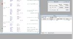
here's the code:


Code ASM - [expand]
1
2
3
4
5
6
7
8
9
10
11
12
13
14
15
16
17
18
19
20
21
22
23
24
25
26
27
28
29
30
31
32
33
34
35
36
37
38
39
40
41
42
43
44
45
46
47
48
49
50
51
52
53
54
55
56
57
58
59
60
61
62
63
64
65
66
67
68
69
70
71
72
73
74
75
76
77
78
79
80
81
82
83
84
85
86
87
88
89
90
91
92
93
94
95
96
97
98
99
100
101
102
103
104
105
106
107
108
109
list            p=12c508a
                #include        <p12c508a.inc>
 
 
;*******CONFIG********
                __CONFIG        _MCLRE_OFF & _CP_OFF & _WDT_OFF & _IntRC_OSC 
 
;*******variables********
TEMP_VAR        UDATA 0x07
sGPIO           RES 1;                                  shadow copy of GPIO
db_cnt          RES 1;                                  debounce counter
dc1                     RES 1;                                  delay counter
on                      RES 1;                                  system on flag
 
;*******RC cal*******
RCCAL   CODE            0x1FF;                  vector reset processor
                RES 1;
 
;*******VECTOR RESET*******
RESET   CODE            0x000;                  effective reset vector
                movwf           OSCCAL;                 factory osc cal
 
 
;*******MAIN PROGRAM*******
 
;*******INIT*******
ini
                clrf            GPIO;                   clean out
                clrf            sGPIO;                  actualizar shadow reg
                movlw           b'110100';              config GP0 GP1 GP4 as outputs, GP3 as in
                tris            GPIO;                   
                movlw           b'1011111';             config internal pull-ups ON
                option;
 
;*******PROGRAMA*******
 
main
                clrf            on;
                clrf            dc1;
                clrf            db_cnt;
 
;wait button press
db_dn
                movlw           .26;                    max count = 20ms/768us = 26
                movwf           db_cnt;                 
                clrf            dc1;
dn_dly  
                incfsz          dc1, f;                 delay 256x3 = 768us
                goto            dn_dly;
                btfsc           GPIO, 3;                if button not press (GP3=1)
                goto            db_dn;                  reset cont
                decfsz          db_cnt, f;              else repeat to archieve max count
                goto            dn_dly;
 
;OUTS
                btfss           on, 0;                  test if flag ON/OFF is active
                goto            liga;
                goto            desliga;
                
;OUT "ON" (GP0)
liga
                movf            sGPIO, w;
                xorlw           b'001001';              activate bit GP0 (saida on) and GP4 (led)
                movwf           sGPIO;                  on shadow reg
                movwf           GPIO;                   
                bsf                     on, 0;                  activate flag ON/OFF                            
                goto            db_up;          
 
desliga
                movf            sGPIO, w;
                xorlw           b'001010';              activate bit GP1 (out off) and turn GP4 led off
                movwf           sGPIO;                  
                movwf           GPIO;
                bcf                     on, 0;                  deactivate flag ON/OFF
 
;wait for button release
db_up
                movlw           .26;                    max count = 20ms/768us = 26
                movwf           db_cnt;
                clrf            dc1;
up_dly
                incfsz          dc1, f;                 delay 256x3 = 768us
                goto            up_dly;
                btfss           GPIO, 3;                if boton is pressed (GP3=0)
                goto            db_up;                  restart count
                decfsz          db_cnt, f;              else repeat until max count is reached
                goto            up_dly;
 
;update outs
                btfsc           on, 0;                  test flag ON/OFF to know wich bit is on
                goto            desliga_out;
                goto            liga_out;
                
;clean out GP0 or GP1
desliga_out
                movf            sGPIO, w;
                xorlw           b'000010';              
                movwf           sGPIO;
                movwf           GPIO;
                goto            db_dn;
 
liga_out
                movf            sGPIO, w;
                xorlw           b'000001';
                movwf           sGPIO;
                movwf           GPIO;
                goto            db_dn;
 
                END


sorry for bad english in program wich is written in portuguese.

hope someone can help me.
 
Last edited by a moderator:

when i put the programmed chip on test board and power up, it lights two led and turn off and it doesn't do nothing from there. i already check the test board connections and its allright.

i use a pic programmer k150 cloned and burn the hex with microburn. after the first programming, i can't program the pic again (i only can read the program on it). but its another issue.

i think the code is allright, the only doubt i have is on configuration parameters (osccal, reset, etc) (until line 19).
i also define a variable to flag when the "on" output was activated it turns 1, it called "on", and i only use a bit of that flag to make the test. i don't know also if the sintax is correct. (line 11 to define, test on line 56, set on line 67, clear on line 75).

if you can look at this points maybe can be a good help.

sorry for the bad explanation, and thanks for the attention


Code ASM - [expand]
1
goto main

is missing. Your program halts without an endless loop. Throw away your PIC. You used 12C PIC instead of 12F. C series are One Time Programmable (OTP) devices. Buy 12F chip.


Code ASM - [expand]
1
movlw           b'110100';              config GP0 GP1 GP4 as outputs, GP3 as in

value is wrong. b'101100' makes GP0 GP1 GP4 as outputs. TRIS register is not set. TRIS should be used to set Input or Output and not GPIO.
 
Last edited:
  • Like
Reactions: zipius

    zipius

    Points: 2
    Helpful Answer Positive Rating
the endless loop is created by
Code:
goto     db_dn;
instruction on the two options after test flag "on". but i can put that in before the end of program labl. in your opinion the flag "on" is well defined and should work correctly?

the output definition is really a big stumble, thanks! :)

and you think that the TEMP_VAR's (ln7), RCCAL (ln14) and RESET (ln18) are correctly? the temp_var's and the rccal is like in the .asm tutorial file in MPLAB for this chip, so it must be right, but the RESET vector should start on 0x000 to place the pointer at the beggining of memory?

i choose this chip because i see on datasheet that the EEPROM data memory has a big number of read/write cycles, but i still have two more ammunitions.

sorry for so many questions but i don't work with pics for a long time.
 

I haven't used that chip, so I will answer later. I have mentioned in my previous post that your device is OTP (One Time Programmable). If the code is wrong then your device is useless. Buy PIC12F. Provide the link from where you got the code. I really have not understood what you want to do. Your first post is not clear to me. Provide a circuit and explain the functioning of each button.
 

the test circuit is something like this:
circuittttttt.jpg

later i'll replace the GP0 and GP1 led by two transistor to drive two relays, because i need 12V outputs.

the functioning is the following: starting with all led off, while the button (GP3) is pressed, the GP0 led turn on, turning off when button is released. the GP4 led stays on. when i push the button again, the GP1 led turns on while the button is pressed and turn off when released. the GP4 led turns off, returning to the initial state.

i never used this chip before too, but i want a very tiny device and this seems to me the best option. i see now that i'm wrong. :|

the code was developed by me, only copied the debouncing part from **broken link removed** page 17 and 18

the point of all this is to control a two button device (power on and power off) with just one button.
 

sorry... :| i'm going to describe the loop cycle:

1st state: all leds off
2nd state: while GP3=0 (button pressed) -> GP0=1 and GP4=1
3th state: GP3=1 (button not pressed) -> GP4=1
4th state: while GP3=0 -> GP1=1 and GP4=0

and now all leds are off and the cycle repeats


circcccuit.jpg
 
Last edited:

sorry... :| i'm going to describe the loop cycle:

1st state: all leds off
2nd state: while GP3=0 (button pressed) -> GP0=1 and GP4=1
3th state: GP3=1 (button not pressed) -> GP4=1
4th state: while GP3=0 -> GP1=1 and GP4=0

and now all leds are off and the cycle repeats


View attachment 97608


Hi,

Your program is basically 2 delay loops of 20ms

In the first loop with the switch off it turns on GP0 , but when it gets to the second loop if the switch is still off, it just sticks within that loop.

Thats as far as I tested, using MPLABs SIM as you can see below.

However your switch programming is not good in practical terms, a mechanical switch is either hardware debounced with say ttl logic or software debounced by the program, the debounced time is normally at least 20ms.
So testing your switch in the middle of a 20ms delay loop is not a good way.


Also not sure if you understood the previous point about you 12C chip.
You can only program it once - you cannot erase or reprogram it - so if your program code was faulty, you must bin the chip.

A 12F 508 chip can be reprogrammed many times.
 

Attachments

  • 000119.jpg
    000119.jpg
    82 KB · Views: 113
  • Like
Reactions: zipius

    zipius

    Points: 2
    Helpful Answer Positive Rating
so you're saying if i create something like:

Code:
delay
                movlw           .26;                    max count = 20ms/768us = 26
                movwf           db_cnt;                 
                clrf            dc1;
dn_dly  
                incfsz          dc1, f;                 delay 256x3 = 768us
                goto            dn_dly;
                
                decfsz          db_cnt, f;              else repeat to archieve max count
                goto            dn_dly;

                btfsc           GPIO, 3;                if button not press (GP3=1)
                goto            delay;

to enter when detect the switch on i should get a better result?

after that i could test a flag to redirect the program to where it was like:

Code:
btfsc     on,0;
          goto     off_loop;
          goto     on_loop;


i understand this pic can only program one time, but i still have two more to burn! i make a mistake not buying the 12F series :(
 

Try using isis proteus first... simulate the circuit before programming...

I'm from Brazil, if you need help, send pm with details of the project. (Eu sou do Brasil, se precisar, posso te ajudar, mande todos os detalhes de seu projeto).
 
  • Like
Reactions: zipius

    zipius

    Points: 2
    Helpful Answer Positive Rating
See if you can convert this to asm.


Code C - [expand]
1
2
3
4
5
6
7
8
9
10
11
12
13
14
15
16
17
18
19
20
21
22
23
24
25
26
27
28
29
30
31
32
33
34
35
36
37
38
39
40
41
42
43
44
45
46
47
48
49
50
51
52
53
54
55
#define _XTAL_FREQ 4000000
 
#include <xc.h>
#include <stdio.h>
#include <stdlib.h>
#include <delays.h>
 
#pragma config OSC = XT
#pragma config WDT = OFF
#pragma config CP = OFF
#pragma config MCLRE = OFF
 
int main(int argc, char** argv) {
 
 
    unsigned char state = 0;
 
    TRIS = 0b001000;
    GPIO = 0x00;
 
    while(1){
        if((GPIObits.GP3 == 0) && (state == 0)){
            __delay_ms(50);
            if((GPIObits.GP3 == 0) && (state == 0)){
                GPIO = GPIObits.GP0 = 1;
                GPIO = GPIObits.GP1 = 0;
                GPIO = GPIObits.GP4 = 1;
                state = 1;
            }
        }
 
        if((GPIObits.GP3 == 1) && (state == 1)){
            __delay_ms(50);
            if((GPIObits.GP3 == 1) && (state == 1)){
                GPIO = GPIObits.GP0 = 0;
                GPIO = GPIObits.GP1 = 0;
                GPIO = GPIObits.GP4 = 1;
                state = 0;
            }
        }
 
        if((GPIObits.GP3 == 0) && (state == 1)){
            __delay_ms(50);
            if((GPIObits.GP3 == 0) && (state == 1)){
                GPIO = GPIObits.GP0 = 0;
                GPIO = GPIObits.GP1 = 1;
                GPIO = GPIObits.GP4 = 0;
                state = 0;
            }
        }
 
    }
    
    return (EXIT_SUCCESS);
}


Status
Not open for further replies.

Similar threads

Part and Inventory Search

Welcome to EDABoard.com

Sponsor

Back
Top