Continue to Site

Welcome to EDAboard.com

Welcome to our site! EDAboard.com is an international Electronics Discussion Forum focused on EDA software, circuits, schematics, books, theory, papers, asic, pld, 8051, DSP, Network, RF, Analog Design, PCB, Service Manuals... and a whole lot more! To participate you need to register. Registration is free. Click here to register now.

Selection of the reference voltage supply circuit and filtering circuit at the reference voltage inputs of the ADC during strain measurement

Auric_

Junior Member level 2
Joined
Jul 30, 2023
Messages
20
Helped
0
Reputation
0
Reaction score
0
Trophy points
1
Activity points
358
Usually, the manufacturer gives standard recommended schemes in the datasheets for the ADC (in this case, for the sigma-delta ADC), and even recommends the values of the elements in the filters (to suppress differential and common mode noise), but I would like to read an alternative opinion. Moreover, there is an alternative in the ready-made circuits of devices that I came across, I just doubt these solutions and I would like to read the opinion of my colleagues about these "non-standard solutions" in order to understand the pros and cons.
Usually in weight measurement, the bridge is connected to 5V (sensor excitation), the reference voltage to the ADC is supplied from this power supply, since the measurement is ratiometric, the stability of the supplied voltage does not affect the ADC readings within certain limits (for example, temperature drift in the power supply).
According to the Texas Instruments circuits on the ADS1220, the reference voltage is connected only with a differential filter (capacitor 90-100nF), the input measuring signal comes with RC + differential (capacitor).
rtd.png
scales.png

Hence two questions:
1. Considering that strain gauges are calibrated anyway, and the transfer coefficient is on average 2mV / V, which indicates that the reference at 5V will be large enough compared to the useful measured signal, which is less than 10mV, how useful / bad is it to take the reference voltage from the divider, bringing it closer to the measurable? I would like to hear all the pros and cons, if you also used this (well, as I understand it, and I saw this in the circuits, they probably wanted to get more accuracy by scaling the reference, leaving the dependences on the input for compensation, but at the same time getting a greater voltage attributable per digit - discrete).

2. for different circuits, the signal to the reference voltage is supplied from the outside, for the thermal resistance from the shunt, for the load cell - from the sensor power supply, but anyway it is "dirty" here and there, because the conductors are located "in the field", that is, interference characteristics identical for different circuits, I personally did not find a difference. So, in order to understand where filters can not be used, and where they are needed, I want to read the opinions of my colleagues, for example, for thermistors in the reference receiving circuit, in addition to the differential capacitor, capacitors are also used from common mode interference (each wire of the reference connected through the capacitor to ground) as part of RC -filter, and for strain measurement, the manufacturer only needs a differential capacitor in the circuit, which makes me misunderstand why the measures are so different under the same initial conditions. The choice of elements is not entirely clear, in one case there are no resistors in the reference voltage circuits, in the other case there are.

3.png

Here is an alternative circuit, where there are dividers and no reference filters, and this happens
 
Hi,

discussion turned form a 5 samples/s application to a 600MHz oscilloscope.

****
I agree there probably is some noise. Maybe in the MHz range.
Simple solution: use a proper PCB layout, install proper low pass filters (anti aliasing filter) --> This (HF noise) problem solved.

Klaus
 
System with a uC in it, internal/external clocks in the 10's of Mhz
range, many now 50 Mhz or better. Caps that struggle at those
freqs to behave as caps. Fun times with FCC, been there, done that.

Regards, Dana.
 
If I´m not mistaken we did not see
* your schematic (all that is involved in the measurement)
* your PCB layout
* your wiring / shileding ... and the different test setups you made.

Textual descriptions simply saying are not suitable to descripe every single informations.
Screen shots, complete schematics, photos ... show the things how they really are.
And they show details that you (with this lack of experieince) simply do not recognize .. to generate an issue. And I don´t meant this to offend you, it´s just a matter of fact.

So if you want us to help you ... I recommend to provide these informations, so we are able to validate the full circuit.
Please reduce the file size of the photos to maybe 100kBytes each so that even members with low internet bandwidth are able to download them.

Klaus
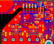
EXC.pngsuplay.pngPCB.png
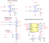
I slightly adjusted the diagram from TIDA-00765 with the realities, it’s easier than pulling it out in pieces from my diagram. For power supply, 24V is taken and supplied to DC/DC, then to the LDO stabilizer, where it is reduced to 3.3V. The power supply to the processor is decoupled using capacitors and FB (ferrite bead), just like the ADC.
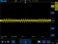
As for the low-frequency noise, it seems like the display driver is guilty, I'll try to run a test without it tomorrow. It’s strange that it gives such a drawdown at 5V, although it is powered by 3.3. By the way, I did a test by supplying 5V to the AVDD from a laboratory power supply, the result was the same as from the “noisy” standard one in the circuit (DC/DC), I did not notice any improvements. Apparently the ratiometric measurement method allows fluctuations in the power supply of the excitation circuits to be compensated.
PS: Yes, that’s right, I disconnected the board with the display and the fluctuations in the 5V power supply disappeared (More precisely, it is correct to say that they became the same as with the supply of power from a laboratory power source), but the measurements still varied (jitter present), I don't think that was the problem was due to the the power supply. As I understand it, we have 10 digits and a dynamic display (one segment is drawn simultaneously on all digits).
20231220225154.png

That is, somewhere around 100 mA there are current inrushes, "dot point" is not used yet, that’s where we see 7 oscillations (7 segments), then a pause on oscillogram.

Although, of course, in the future I need to think about how best to decouple the sources of power supply so that they (or consumers) do not interfere with each other. Probably it makes sense to install a separate DC/DC on the display?
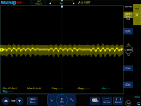
By the way, I tried to increase the capacitance of the capacitor for powering the LED display driver, add 3300uF to 330uF, the ripple decreased slightly, but was still noticeable.
20231223180438_с_кондером_3300_но_руками_шум.png
 
Last edited:
Hi,

The second schematic is of bad quality. Don´t know what it shows.

***
You say there is a 10 digit LED display?
Maybe it´s even multiplexed. So what worst case current pulses do we talk about?

And if you want us to validate your display ... then show us the according schematic and PCB layout.
It´s post#44 now .. and we slowly get information by information.

******

So, how do you whish to go on?
Buying a 600MHz scope ... or finding a soution?

Klaus
 
View attachment 188074View attachment 188076View attachment 188077
I slightly adjusted the diagram from TIDA-00765 with the realities, it’s easier than pulling it out in pieces from my diagram. For power supply, 24V is taken and supplied to DC/DC, then to the LDO stabilizer, where it is reduced to 3.3V. The power supply to the processor is decoupled using capacitors and FB (ferrite bead), just like the ADC.
As for the low-frequency noise, it seems like the display driver is guilty, I'll try to run a test without it tomorrow. It’s strange that it gives such a drawdown at 5V, although it is powered by 3.3. By the way, I did a test by supplying 5V to the AVDD from a laboratory power supply, the result was the same as from the “noisy” standard one in the circuit (DC/DC), I did not notice any improvements. Apparently the ratiometric measurement method allows fluctuations in the power supply of the excitation circuits to be compensated.
PS: Yes, that’s right, I disconnected the board with the display and the fluctuations in the 5V power supply disappeared (More precisely, it is correct to say that they became the same as with the supply of power from a laboratory power source), but the measurements still varied (jitter present), I don't think that was the problem was due to the the power supply. As I understand it, we have 10 digits and a dynamic display (one segment is drawn simultaneously on all digits).
View attachment 188083

That is, somewhere around 100 mA there are current inrushes, "dot point" is not used yet, that’s where we see 7 oscillations (7 segments), then a pause on oscillogram.

Although, of course, in the future I need to think about how best to decouple the sources of power supply so that they (or consumers) do not interfere with each other. Probably it makes sense to install a separate DC/DC on the display?
By the way, I tried to increase the capacitance of the capacitor for powering the LED display driver, add 3300uF to 330uF, the ripple decreased slightly, but was still noticeable.
View attachment 188086
Your comments and scope photos have yet to define the fundamental frequencies. Can you do that? There will be low rep rates with harmonic cycles such as above.

Either give the periods , T1,T2 ... or the fundamental f1,f2, 's and your best guess where that comes from and how your effects make it worse or better (apart from capture noise), such as ground noise, supply noise, load generated noise, spurious radiated noise.
 
I apologize, I'm a little out of the forum communication space.
A little about the results and the accumulated tasks: the ripples in the last and penultimate picture of post 43 (AC mode of the oscilloscope - oscillations on the excitation wires of the measuring bridge) are definitely caused by the consumption of the display, there are 10 digits of 7 segments. At this stage, there is no way to remove the ripple, as most likely the display will need a separate power supply - it consumes so much in pulses that even installing a 3300 uF capacitor on the display board did not help to significantly reduce them, and installing a choke between the boards is not yet possible makes sense because there is no place to put it. Yes, and there is no point, because I conducted another experiment, which showed me that the maximum was reached on this test bench - by connecting the measuring bridge to two other devices, one of which has an ADC of as much as 32 bits, and to the other, which has a good circuit and is also a 24-bit ADC, I did not see the stability of the readings greater than mine, that is, pulsations of the order of +-1 gram against a background of 20,000 grams were present in all measurements, in fact, as I said, this suits me in this task, I just wanted to understand how in the article from Texas Instruments guys achieved stability, most likely they heavily filtered the signal.
And my oscilloscope let me down, I expected that FFT would work as it should, but for some reason it did not give me spectrum decomposition, and in fact, as I already wrote, even these fluctuations in the excitation signal are not the cause of the scatter, they simply work on At the maximum, even by knocking on the table I can cause the system to undergo large fluctuations in the measured value.

By the way, regarding post #12 with which I continued the topic and which eventually gave birth to the rest of the discussion thread, judging by the description of other devices, usually manufacturers themselves leave the settings to the user, setting options for choosing both the number of samples in averaging and the number of weight measurements.

But in general, thank you all for your participation, I rechecked my understanding in some places, and in some places I even learned something new. If anything, I will return to this topic when new equipment appears (measuring weighing cell), for which I see that the measurement accuracy and stability are higher according to the readings on more accurate instruments. Moreover, the current board is also awaiting improvements in the next iteration. In the meantime, there is still a lot of coding to do...
 
  1. I think it is easier to have a stable voltage regulator for the low current sensitive stuff and leave the noise outside the V+ and ground loop of your measurement system.
  2. A.gnd and D.gnd should never share currents in routing wires and traces. This can alter your Vref in the ADC, even with perfect CMRR in your INA.
  3. Adding caps and chokes on a shared ground won't solve the problem.
  4. Using a CC source rather than a CV source for the bridge will improve PSRR.
  5. Desk vibrations ought to generate a few grams of force unless your bridge was mounted on a granite slab like that used for laser holography. I used to have a seismic design that could measure my knee flexes standing on the basement floor of the geology building with a geophone as well as pick up all the A/C blower vibrations in the building.
  6. With one 1 sensor you can use only 2 wires using CC source to measure the voltage by resistance changes in the strain gauge by measuring across the CC source.
  7. I still don't know how many sensors you have in your bridge. 2 are better than 1 (1 compression and 1 expansion) and 4 will null out thermal errors with 4 times the sensitivity.

  1. I still don't know how many sensors you have in your bridge. 2 are better than 1 (1 compression and 1 expansion) and 4 will null out thermal errors with 4 times the sensitivity.
 
Last edited:

LaTeX Commands Quick-Menu:

Part and Inventory Search

Welcome to EDABoard.com

Sponsor

Back
Top