Welcome to our site! EDAboard.com is an international Electronics Discussion Forum focused on EDA software, circuits, schematics, books, theory, papers, asic, pld, 8051, DSP, Network, RF, Analog Design, PCB, Service Manuals... and a whole lot more! To participate you need to register. Registration is free. Click here to register now.
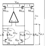
In the attached sub 1V bandgap reference circuit, the voltage across R3b should be a PTAT. In simulation I get a CTAT for both the legs. What could be the possible reasons?
It's all about the resistor tempco. "CTAT" is a narrow subset
of PTAT outcomes. That is, where the "proportionality
constant" is zero (-ish).
You can see very different core cell behavior with a zero-TC
thin film resistor, or a high-TC lightly doped silicon one, or
a grain-boundary-dominated high-sheet poly resistor (and
this latter, has terrible "make" tolerance against a roughly
uncontrolled poly grain size & qualities.
Of course there could be other details like a poor choice
of core area ratios at play, or an amplifier which has its own
countervailing Vio drift, or ....
This site uses cookies to help personalise content, tailor your experience and to keep you logged in if you register.
By continuing to use this site, you are consenting to our use of cookies.