Continue to Site

Welcome to EDAboard.com

Welcome to our site! EDAboard.com is an international Electronics Discussion Forum focused on EDA software, circuits, schematics, books, theory, papers, asic, pld, 8051, DSP, Network, RF, Analog Design, PCB, Service Manuals... and a whole lot more! To participate you need to register. Registration is free. Click here to register now.

Selection of the reference voltage supply circuit and filtering circuit at the reference voltage inputs of the ADC during strain measurement

Auric_

Junior Member level 2
Joined
Jul 30, 2023
Messages
20
Helped
0
Reputation
0
Reaction score
0
Trophy points
1
Activity points
358
Usually, the manufacturer gives standard recommended schemes in the datasheets for the ADC (in this case, for the sigma-delta ADC), and even recommends the values of the elements in the filters (to suppress differential and common mode noise), but I would like to read an alternative opinion. Moreover, there is an alternative in the ready-made circuits of devices that I came across, I just doubt these solutions and I would like to read the opinion of my colleagues about these "non-standard solutions" in order to understand the pros and cons.
Usually in weight measurement, the bridge is connected to 5V (sensor excitation), the reference voltage to the ADC is supplied from this power supply, since the measurement is ratiometric, the stability of the supplied voltage does not affect the ADC readings within certain limits (for example, temperature drift in the power supply).
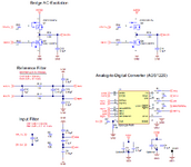
According to the Texas Instruments circuits on the ADS1220, the reference voltage is connected only with a differential filter (capacitor 90-100nF), the input measuring signal comes with RC + differential (capacitor).
rtd.png
scales.png

Hence two questions:
1. Considering that strain gauges are calibrated anyway, and the transfer coefficient is on average 2mV / V, which indicates that the reference at 5V will be large enough compared to the useful measured signal, which is less than 10mV, how useful / bad is it to take the reference voltage from the divider, bringing it closer to the measurable? I would like to hear all the pros and cons, if you also used this (well, as I understand it, and I saw this in the circuits, they probably wanted to get more accuracy by scaling the reference, leaving the dependences on the input for compensation, but at the same time getting a greater voltage attributable per digit - discrete).

2. for different circuits, the signal to the reference voltage is supplied from the outside, for the thermal resistance from the shunt, for the load cell - from the sensor power supply, but anyway it is "dirty" here and there, because the conductors are located "in the field", that is, interference characteristics identical for different circuits, I personally did not find a difference. So, in order to understand where filters can not be used, and where they are needed, I want to read the opinions of my colleagues, for example, for thermistors in the reference receiving circuit, in addition to the differential capacitor, capacitors are also used from common mode interference (each wire of the reference connected through the capacitor to ground) as part of RC -filter, and for strain measurement, the manufacturer only needs a differential capacitor in the circuit, which makes me misunderstand why the measures are so different under the same initial conditions. The choice of elements is not entirely clear, in one case there are no resistors in the reference voltage circuits, in the other case there are.

3.png

Here is an alternative circuit, where there are dividers and no reference filters, and this happens
 
power supply, but anyway it is "dirty" here and there, because the conductors are located "in the field",

The greater the impedance in your wiring, the easier it is for outside interference to influence your project. Therefore the lower ohms in your sensor wires, the less the interference.

Easy method to isolate (partially) your sensitive device from noise in the power supply:
The smooth scope trace has noise filtered out. The noise is the triangle wave:

filter noisy supply via resis-and-cap to sensistive device.png
 
Hi,

The usual way is that your application decides tze requirements ... and according these requirements you choose the circuit.
Thus I miss your requirements.

For strain gauge measurement:
* always use the same source for supplying both the sensor and the ADC_VRef.

1)Regarding range adjust by scaling down VRef:
* you usually don't get higher accuracy by scaling down VRef. Nor do you get higher precision. Both are expected to become worse. You get better resolution
* there is no clear answer, what's the best way: it depends on the ADC specifications and your application requirements.
* in the upper schematics there is an PGA inside the ADC to amplify the analog input signal. --> use it

2)
* if you use filters, then apply the identical filter (characteristic) for both. (Source-> filter->sensor and Source->filter->ADC_VRef)
Regarding this the CS5509 schematic is not optimal.
You can see that there is no filter from VCC to VRef. Thus the digital (output of ADC) noise clearly depends on VRef noise. VCC usually is not as clean as one expects a VRef to be. --> filter VRef.

My general rules:
Don't attenuate signals (analog input as well as VRef) unless it is necessary (to meet input voltage range, for example).
Also mind that an amplifier can't improve SNR of an analog signal. Since it amplifies signal as well as noise.
Amplifiers always add errors like noise, dustortion, offset ... and all of this may drift with temperature, time, supply voltage...
Use filters to attenuate noise (frequencies) beyond the wanted analog signal bandwidth.

Klaus
 
I apologize if this is a stupid question, but using the documentation I did not find a clear understanding.
I want to implement alternating current excitation of the load cell on the ADS1220, but for correct measurement it is necessary that the REFP signal be greater than REFN. I planned to switch REF0 and REF1 on the fly using SPI commands, and REFP and REFN themselves are already physically connected in the required polarity, for example REF0 for direct, and REF1 for reverse polarity of load cell excitation. In theory, if the input is not selected as the reference voltage, it does not matter what the polarity is, but I am interested in the moment when I have already changed the polarity and have not yet changed the settings, how the ADC will behave if an incorrect reference voltage is supplied to the inputs of the reference signal within the limits standards for powering the ADC, but REFN will be greater than REFP, contrary to the instructions. Will this usually only cause inaccuracy in the operation of the ADC measurement circuit, or are there worse problems - for example, will there be an operating mode in which something can deteriorate (burn out) in the ADC itself? Is it necessary to avoid this mode by transitioning to an intermediate state, when, for example, the internal reference is selected, and then, after switching the power supply, set the required inputs as reference?
It's just that extra commands are a waste of time.
 
Hi,

No, not a stupid question.

AC exctitation is the more sophisticated, more accurate version, but - yes - more complicated.
There are two major benefits:
* get rid of DC voltages caused by thermocouple effects
* focussing on exactly one frequency, filtering out errors like noise, distortion and so on...

Possible solutions:

1)
For AC excitation I usually use an ADC with two differential inputs and simultaneous sampling.
Measure the excitation voltage and the sensor signal voltage (amplified).
then do a correlation between these two signals

2)
Generate the excitation with a precision DAC .. synchronous sampling of DAC and ADC.

3)
in your case, if you want to keep the existing ADC.
( I did not read the ADC datasheet, thus one needs to be sure the Ref can contain AC)
Keep VRefN at lowest level.
Generate VRefP as sine, but biased with DC so it satisfies VREF specification.
Then on the digital side get rid of the DC and just process the AC (amplitude).

4)
in your case, if you want to keep the existing ADC.
Keep VRefN and VRefP constant.
Generate just the excitation signal AC with precise amplitude.
Then on the digital side (get rid of the DC and) just process the AC (amplitude).

Hope this helps so far.

Klaus
I just can’t understand how the ADC will behave. I plan to do the excitation for a quick assessment without alternating current, and when the weight is close to being gained, switch the direction of the excitation current and measure the weight value in pairs of measurements with one and the other polarity, this is how the EMF of the parasitic theomacouples should be compensated.
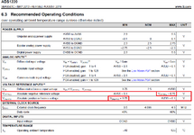
The documentation item about ADC is confusing:
ADS1220.png
There is a range indicated in which VREFP mast be greater than VREFN, but nowhere is it described what will happen if this condition cannot be fulfilled. Moreover, it is not planned to measure in conditions when VREFP is less than VREFN, contrary to the instructions, I just need an understanding that the ADC itself, provided VREFP is less than VREFN, will not lead to failure of the ADC (damage, not an error, errors are not terrible, at this moment no measurements are made , just a transition moment between switching VREF channels of ADC). Why am I confused? An extra SPI transmission packet to disable VREF at the time of excitation switching lengthens the cycle of work with the ADC.
EXC.png
As can be seen from the picture from the design reference ADS1220, the reference voltages are taken from the excitation, which is powered via a bridge circuit. If reference input 0 receives direct polarity (REF0 to REFN), then reference input 1 receives reverse polarity (REF0 to REFP). The REFN and REFP inputs are not always selected as a reference for the ADC; in fact, they are selected by the SPI settings. And if in the case of a bridge circuit you can simply make a dead-time pause to switch the polarity of the excitation, then in my case (I have a microcircuit that produces polarity immediately from one control input: if 0 one polarity, if 1 reverse, and does not allow to make dead-time pause) this cannot be achieved and either I have to turn off the reference for a while from the REFN and REFP pins of the microseme (not very convenient, we're wasting time), or we force ADC to work the into a mode that is not described in the documentation, when changing polarity before switching or switching before changing polarity, exactly one of the selected reference inputs (0 ore 1) will catch the mode when VREFP is less than VREFN.

Unfortunately, I did not find at least one circuit that would consider how a typical sigma-delta ADC with ratiometric measurement works, more precisely when the reference voltage is set by more than one input relative to zero, but there are two inputs REFP and REFN, which are not tied to AVDD nor to AVSS.
 
Last edited:
If you worry about operation conditions that can cause possible damage, you consult absolute maximum ratings (datasheet page 5). Reversed reference within maximum ratings shouldn't cause damage, but of course, can't give useful measurements.
 
For example AD7730 can accept input signals from a DC-excited bridge or an AC-excited bridge by using the AC excitation clock signals (ACX and ACX ). These are non-overlapping clock signals used to synchronize the external switches which drive the bridge. The ACX clocks are demodulated on the AD7730 input.

This way if the remote signal being sensed shares a return path with DC current causing a DC voltage offset, then the AC excitation method will null this error.

The REFP, REFN are provided to offer ratiometric conversions, not to rectify or reverse alternating polarities of signal and demux in any ADC.

1702741685994.png


--- Updated ---

For the ADS1220 you cannot swap polarities of the voltage REF(N,P) and the differential inputs may be true differential for best common mode rejection using shielded twisted pairs or may be used with DC on AINn and stay within the defined limits.
1702741177047.png
 
Last edited:
For future reference you can do this on a SOC, single chip, as shown few resources were used.

Compiler and IDE (PSOC Creator) free, board ~ $20 (CY8CKIT-059). Note precision Vref is onchip as well.
A/D on chip 20 bits, with 1.024 Vref resolution is basically 1 uV.

1702742747359.png


Whats also onchip, multiple copies in many cases :

1702742822685.png


Regards, Dana.
 
Unfortunately, I did not find at least one circuit that would consider how a typical sigma-delta ADC with ratiometric measurement works.

Falstad's animated interactive simulator contains a Delta-Sigma ADC circuit which lets users alter operating characteristics.
Click the Circuits menu, choose Analog-Digital, and select a circuit.

falstad.com/circuit

I changed the time-step from 5u to 50u so all the waveforms take shape on one screenshot:

screenshot Delta-Sigma ADC (Falstad's).png
 
Hello again. I tried controlling the excitation of the weight sensor using the UCC27525, judging by the oscillogram, I made the delay equal to 1 ms after switching the polarity. Depending on the polarity, I change REF0 or REF1 as the channel for measuring the reference voltage, and the polarity of the signals from the excitation voltage is inverted, so at the time of starting measurements in single-shot mode, I set the correct mode for the ADC, select the desired channel for the polarity and waiting for the excitation voltage to stabilize. In principle, the ADC normally perceives this mode of operation, what I wrote about earlier is that after switching, the ADC itself is physically forced to be powered for some time (not at the time of measurement, of course) according to a not entirely suitable circuit until the software switches the REF channels, when the voltage at the REFP input is lower than on REFN. This is so purely practical.
And the question I have now is this: noise... when choosing the mode for the ADS1220 Normal mode and the minimum possible speed (data rate) for this mode equal to 20SPS, good stability of the readings is obtained, for this I did not even need to connect the grounding conductor, but I still wanted to get more high performance (data rate), so that later I can use software filters and not lose performance (speed of reaction), because the noise in laboratory (clean) conditions is clearly lower than what it will be in real conditions. But what is not clear is that for the Turbo mode it is indicated that the ADC operates at double frequency, which makes it possible to obtain twice the performance with virtually no reduction in characteristics. If you look at the characteristics for Normal mode: Noise in μVRMS (μVPP) for DATA RATE 20 SPS: 0.09 (0.41), for Turbo mode: 0.09 (0.55), but for DATA RATE 40 SPS. Noise-Free Bits from RMS Noise for Normal mode 18.49 for 20 SPS, and for Turbo mode the same as 18.40, but for 40 SPS, that is, quite identical numbers. In fact, if I set the Turbo mode, the noise is such that it chatters worse than if I select the 45 SPS mode in Normal mode, although the characteristics there are noticeably worse: 0.12 (0.51) and 18.00, respectively. By the way, both when choosing Turbo mode and when choosing DATA RATE 45 SPS Normal mode, the influence of the presence of a connected ground conductor is very noticeable.
Considering that I’m not an expert, I can’t understand why Turbo mode performed so poorly for me?
In addition, I would like to understand which way is better to go: increase the number of samples while significantly spoiling the quality of the measurement by introducing noise, and use software filters, or still leave a clean signal with a low DATA RATE, but at the same time not be able to use software filters, as this is significant will reduce the response (slow down the response) of the device to changes in weight (considering that I planned to dosage using the measuring cell, I will have a large delay, which is also very inconvenient).
 
Last edited:
Hi,

In this case I´d only swtich the excitation but not the REF.
I mean: it´s extremely simple to switch polarity of the measurement results on the digital side.

****
But you say you wait for 1ms after switching. This surely is not sufficient for a 20Smpl/s Delta/Sigma ADC. Read it´s datasheet about settling time.

****
If you mean "speed" then please write "speed", because "performance" can be a lot of different qualities.

****
You talk about "low noise" ... and that you expect it to be lower noise in the lab. This is not necessarily true. A good design may work in the field as good as in the lab.
In the lab you have additional noise sources, no metal case / shielding, mains powered power supplies, connected measurement devices like scope ....
All adding a lot of noise.

****
In addition, I would like to understand which way is better to go
A good design starts with specifications.
--> first decide what performance (noise, speed, linearity, offset, drift ...) you expect, then do the design accordingly.
--> Numbers with units. No vague textual decription like "Better" or "best possible" ..

Klaus
 
Hi,

****
But you say you wait for 1ms after switching. This surely is not sufficient for a 20Smpl/s Delta/Sigma ADC. Read it´s datasheet about settling time.

****

Klaus
For now, I will try to answer only on this point: if I understood your comment correctly, then you are saying that I need to hold the signal longer, as the measurement will not have time to complete, but I am talking about the delay time from changing the polarity to sending a command to the ADC to start the measurement . That is, the measurement itself lasts from the start to the readiness signal, I do not reduce this time in any way, but I need the time before the start, because the signal on the excitation channel has not yet stabilized and here 1ms is enough, I tried more - I did not see the difference.
Although maybe I didn't understand something
 
Hi,

There are different Delta/Sigma ADCs. Usually S/D ADCs use a continous clock for continously sampling data.
Usually you can´t trigger single conversions and read the result. Usually you need to do many conversions first (with stable input) before you get a valid output.

It´s not that same as with SAR ADCs where you can trigger each single conversion ... and get a valid output each single time.

This is why many S/D ADCs are not very useful when switching input (and REFerence) conditions. (What you try to do)

--> Thus again my recommendation to read the datasheet thoroughly.

Klaus
 
Hi,

***

A good design starts with specifications.
--> first decide what performance (noise, speed, linearity, offset, drift ...) you expect, then do the design accordingly.
--> Numbers with units. No vague textual decription like "Better" or "best possible" ..

Klaus
since this is a hobby, or rather study combined with a hobby, I don’t have specifications, but I can list my initial guidelines, which I use as a guide in general: as I wrote earlier, I assembled the diagram based on TI Designs TIDA-00765 (Schematic - TIDA-00765), search engines will provide comprehensive information, that is, I have filters on the measuring channel of 1 kOhm resistance connected in series, one in each channel, and common-mode capacitors 0.01uF, one in each channel and one 0.1uF against differential noise. On the reference voltage channel with the same cutoff frequency, but slightly different parameters: 100 Ohm resistance, 0.1uF capacitors, one in each channel and 1uF against differential noise. The really confusing thing is that Texas gives CM f-3dB = 339 kHz DM f-3dB = 16.1 kHz filters, but in fact, based on calculations, it turns out to be 16 kHz for common-mode and 0.8 kHz for differential noise, although of course I could be wrong. The frequency is the same for both the measuring channel and the reference voltage.
ADS1220 ADC, measurements in single-shot mode, that is, in start-stop mode, controlled by commands (start via SPI, request for results by interrupt, issued by a discrete signal from the ADC when measurement is ready).
I have a similar device (or rather, I even looked at two different ones, but at the moment there was only one left for testing, I looked at the design, the diagram of the measuring part, and studied the general principles). I wanted to get characteristics that were not worse. I have a sensor of 1 mV/V sensitivity, calibrated for a weight of 20 kg, I wanted to get at least stable up to a gram (like in the same as in TIDA-00765). But at the moment, as I wrote, with a number of samples of 45 per second, my gram is unstable, more likely +-1g, that is, it can show values of 1, 2 or 3 grams within a second. Considering the expected effective resolution of the ADC is 18 bits (effective number of bits - ENOB), we have an expected stability of around 0.1 grams, well, at least half a gram, considering that we got a less-than-ideal version of the ADC, but for me the accuracy suffers more significantly. The device I am comparing can reliably display with an accuracy of up to a gram, even up to 0.2 grams with the same sensor (it has AD7799 ADC with 24bits resolution, I think the efficiency is similar to ADS1220). I have not yet checked the measurement precision, linearity with reference scales, as well as drift, but I don’t think that the filter parameters (both physical and software) will increase them significantly. But I can definitely say that the speed of the reaction suits me now (now I am averaging 3 values of two pairs of measurements with different excitation polarities, that is, the average of 6 measurements), but if I average 30 values of the moving average, the readings will stabilize, but the speed will drop significantly. Even averaging 10 values gives a slowdown that is not acceptable to me.
 
Last edited:
Please provided any plots of error results so we can analyze spectrum.

Often line noise gets in as CM and due to lack of shielding or balance converts to DM.

The 50 or 60 Hz can produce "alias effect" (difference frequency) errors. The datasheet shows the optimum sampling rates for both.

The other factor is noise filtering BW based on BW(-3dB)= 0.35/RC ought to be well below sampling rate for any interfering frequency to both Vdm and Vref. This is a Nyquist criteria, even though there is good digital filtering. I don't know how sensitive the external filter and noise affected your results.

I suggest you keep the DM signals short and use STP wire with PE earth bonded shield then see how the cap. values you chose affect RC BW and results.
I'll try, but for now there are difficulties - the RS485 channel most likely will not provide the required polling frequency to create a date logger, at least for now, the program that I have cannot keep up, requests are sent via Modbus, this also loads the channel with additional data upon transmission. I’ll try to accumulate in STM32 and request in batches, but for this I will need to write my own program for a PC.
By the way, I noticed that there is also a significant drift over time, which can shift the readings for a 20kg sensor by as much as 10g within a few minutes, that is, the device can show more or less consistently 0g, and then after a while the readings smoothly go up to 10g. The weight on the sensor (physically) naturally does not change. Then these readings may come back to 0g.
I don’t understand what caused this...
 
Hi,

weight measurement usually is rather low frequency. One usually does not need a data rate of more than 5 per second.

In post#16 you talk about frequencies in the kHz. It is at least two (or three) magnitudes above what you need for a weigh scale.
Maybe you did chose an inappropriate IC at all. There are dedicated weigh scale ADCs (data acquisition systems).

Now you think that RS485 is too slow .. I can´t see why. RS485 bandwidth should easily go up to 1MBaud .. which should be suffiicient for way above 25kSamples/s.
In the previous posts I don´t see where RS485 is involved at all. So this new information just confuses me.
Also "MODBUS" is new information.
(Regarding MODBUS it depends what are the other connected devices on the MODBUS, other device´s data rates, baud rate options)

I also did not find the "data logger" information in the previous posts. If you post informtions piece-by-piece it´s not our fault to provide unsuitable recommendations.

Also "PC program" and "wrting on your own" ... is just another topic. I con only recommend: draw a signal flow sketch and solve the issues one by one form source to destination. Mixing all together is not very effective.
****

Drift over time: Simple to analyze.
Drift can be "offset drift" which does not relate to the applied weight (zero wight).
or it can be signal related: like "gain drift".
simply: if zero weight is applied and the result drifts by 0g +/-10g then it is offset drift.
If is is not offset drift, but you see the +/-10g drift only when 20kg is applied, then it is signal related. (Gain drift, Ref drift ...)

+/-10g on a 20kg load is 0.1% or just 10 bits of reliable information. --> No need for a 16 bit or even 24 bit ADC.

****
again: focus on one problem. Solve this problem, then go to the next problem. From source (sensor) to destination (PC)

Klaus
 

LaTeX Commands Quick-Menu:

Part and Inventory Search

Welcome to EDABoard.com

Sponsor

Back
Top