Continue to Site

Welcome to EDAboard.com

Welcome to our site! EDAboard.com is an international Electronics Discussion Forum focused on EDA software, circuits, schematics, books, theory, papers, asic, pld, 8051, DSP, Network, RF, Analog Design, PCB, Service Manuals... and a whole lot more! To participate you need to register. Registration is free. Click here to register now.

Unknown Dc voltage at the output of the circuit

mtnkh

Newbie level 6
Joined
Mar 1, 2021
Messages
14
Helped
0
Reputation
0
Reaction score
0
Trophy points
1
Activity points
164
Hi everyone,

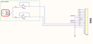
I have come across an issue in a circuit that I would like to discuss. The circuit, shown below, exhibits an offset in the output. The output is given by (AI-5+) - (AI-5-). To investigate further, I short-circuited the input on the left side and observed that the output in this case is equal to 84mV. The resistors R1 and R2 are both set to 100Kohm.

Furthermore, I simulated the circuit using Ltspice, and the output consistently measured almost 84mV. I experimented with different values for R1 and R2, but the output voltage remained unchanged. Therefore, it seems that the offset is not due to the bias current of the OpAmps.

However, I am unable to determine the source or cause of this DC voltage. I would greatly appreciate it if someone could provide an explanation for this phenomenon.

Thank you in advance.

temp.png
 
Hi,

how have you measured the 84 mV, with a DMM or an oscilloscope?
Are the 84 mV the difference voltage or for an single output?
Have you tied the two inputs (J2) together or have you tied them to ground?
Are the outputs of your opamps floating, or does your DAQ connection represent a defined load?
What's the supply voltage of the opamps?
It seems one output (opamp pin #7) is connected to something else, not visible in the picture.

BR
 
You're missing a lot of information:
Power supplies.
Input voltage.
What "A1-5" means.
Load.

Read the data sheet.

Output LOW voltage could be as high as 325mV with a 5mA load.
 

    mtnkh

    Points: 2
    Helpful Answer Positive Rating
Hi,

how have you measured the 84 mV, with a DMM or an oscilloscope?
Are the 84 mV the difference voltage or for an single output?
Have you tied the two inputs (J2) together or have you tied them to ground?
Are the outputs of your opamps floating, or does your DAQ connection represent a defined load?
What's the supply voltage of the opamps?
It seems one output (opamp pin #7) is connected to something else, not visible in the picture.

BR
*I measured the voltage with a analog to digital module as it is shown in the picture.
* No it is not for a single output. It is the difference between U2A Opamp and U2B Opamp output. In the right side of the picture you see the J1 connector, the difference between p10 and p11.
* I tied them together .I attached another picture to show it in a better way.
* No there is not any load I want to measure the buffer's output.
*Vss = 5v and Vee = -5v
*I attached a better picture, no it is not connected to anything else.
* The groiund of the DAQ is connected to the ground of the circuit.

Thanks
 

Attachments

  • temp.png
    temp.png
    69.9 KB · Views: 78
Your input V is unknown right ? So question are the inputs in
input CM range ? If not all bets are off. Tie them to a known V,
including ground, to insure they are operating in CM range.

1686007985504.png


Regards, Dana.
 

    mtnkh

    Points: 2
    Helpful Answer Positive Rating
Floating inputs are not your friend.
In fact, this circuit is related to the microneedle electrodes which are attached to the the skin surface in order to measure the voltage difference between two parts of the body, the electrodes are buffered by using Opamps to decrease the noise. So in this case in the right side of the picture, J2 connector, "1" is attached to the first electrode and "2" is attached to another electrode. When I was measuring the difference voltage at the ouput, I mean with DAQ, the signal between "10" and "11" I was unsure I'm measuring the right voltage in this case I connected "1" ans "2" in J2 connector to see if there is any offset at the output which it shows 80mv. In this case I don't have any load at the output. Do you have any suggestion?

Thanks
 
Your connections input side look like this :

1686015354567.png


Ref connection, gnd, supplies the bias ....


Regards, Dana.
 
As noted, you need a ground reference connection to the subject you are measuring, and you need to ground the input to measure the offset.
The inputs must have a path to ground (even if it's a high impedance).
 

LaTeX Commands Quick-Menu:

Part and Inventory Search

Welcome to EDABoard.com

Sponsor

Back
Top