Continue to Site

Welcome to EDAboard.com

Welcome to our site! EDAboard.com is an international Electronics Discussion Forum focused on EDA software, circuits, schematics, books, theory, papers, asic, pld, 8051, DSP, Network, RF, Analog Design, PCB, Service Manuals... and a whole lot more! To participate you need to register. Registration is free. Click here to register now.

[SOLVED] Pic 16f876a Pure Sinewave inverter

Status
Not open for further replies.
all your values are correct except b/a, it depends on MOSFET Rds and output current magnitude, approx. 1 - 2V max.

here are the comparable values

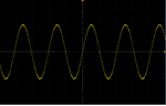
• V_OUT = 2.5V +/- max 1.5V (min 1V, max 4V, middle point 2.5V, sine wave)
• curr_h = 2.5V +/- max 1V (min 1.5V, max 3.5V, middle point 2.5V, sine wave)
• curr_l = 2.5 V +/- max 0.25V (middle point 2.5V, sine wave)
• volt = 4.45 - 4.82 Vdc
• Stdby = 0 - 5 Vdc
 

Hi jami007 & Californijoe, sorry:shock: i forgot to connect curr_h/l to MCU. My inverter start to run and it does work:grin:, but I had to put trimmer in "V_out" because the voltage in A-B is the 12Vac.

Now the value b/a is \approx 0.2V when the inverter is normal mode, but is 2.54V when my inverter is in stdby mode. One question, Is it necessary resistor 1k between b/a-GND?In my inverter is necessary. Thanks!

Regards:grin:
 

hello everybody!!

My inverter does work, my output voltage don't drop, it's correct. I had changed Vac_1 for Vac_2 and my inverter does work:p:p:p!!!!
My problem is the output voltage is 170Vac because Va-b is the 7.5V. It's very important the feedback!!!

yuhuuuuuuuuuuuuuuuuuuuuu!!!!:p
Thank you very much californiajoe & jami007!!
Best regards
 

Attachments

  • output voltage.png
    output voltage.png
    40.8 KB · Views: 195

I am happy for you. Can you desribe more preciselly what did you do?

Regards
 

congratulations, atlast it works, so never forget to share your experience and results..........original credit goes to Taner who made it and share it....

*** Bless You
 

Thank you very much Californiajoe & jami007! :p:p

My problem was the output voltage drop 30V when i was connecting a load 50W, this problem happen because all feedback was trimmer. You tell me to proper work of inverter I must connect all feedback. Then I connected all my feedback, but the value of V_out was not correct. After I read the document on the operation of this inverter that i must tolerate the polarity of voltage, so as I changed "Vac_1" for "Vac_2". My inverter it does work!!!:p:p.

Note: When I connect V_out to MCU,output voltage don't drop 30V, but if i don't connect V_out to MCU, my output voltage drop 30V when i connected a load.

Now my problem is the output voltage is 178Vac (not 230V), but i was worried because my output voltage drop. Did you understand me?:wink::wink:

When I finish all my inverter, i will write a list of component because everybody can to do this inverter. Also I will comment all my experience.

Note: I must connect resistor 1K between b/a-GND

Best regards;-)
 
Last edited:

Hello everybody!!
I want to say that my problem is the output voltage are 178Vac (not 230V). I used software: sine_pwm_voltage-regulator_without_a-b_voltage_check, my output voltage are 230V!!!!:grin:

Californiajoe, you tell me in other post:
"One more thing: I just noticed that pin 2 of 16f876a had to high voltage on it (over 4V) and there was no PWM and A/B signals from MCU. After connection of the resistor ( 1k ) from pin 2 and GND inverter started to run."

Is extremely necessary to connect resistor 1k between pin 2 MCU to GND?
Best regards!:wink:
 

I did it just for test. With correct feedback signals there should be less then 1 volt on pin 2.

Regards
 

I think, it is already done what you are looking for. My advice is to read everything from the begining, could be helpful.

Regards
 
  • Like
Reactions: trapno

    trapno

    Points: 2
    Helpful Answer Positive Rating
Hello to all
Please help me, I think my PIC is broken at the pin 5 (V_BAT)(I put directly 12V wrong in it).
Now voltage for this pin is 0.4V.
Can I re-program (change the analog input) for this project?
I' m beginner in c program

Best regard
 

Hi,
You can try your luck, but i'am afraid the chip may be gone for good

Regards
 

hey guys after successfull completion of our project, now i'm thinking about converting square wave inverter into sine wave inverter, whats your plan?
 

there are two options

1- convert square wave into sinewave with 100% efficency
2- generation of sine wave output using microcontroller with exsisting/little modification in circuit
 

Well in case of option 2, I would join to experiment. Can you please describe both of options preciselly?

Regards
 

I'm starting research, the best one is the option 2, so in this I'll try to use basic principle from taner's project, fast and controlled switching of MOSFETs/IGBTs, i'm beginer in pic coding so I need your help for editing taner's code into simple pwm generator/controller with out any feedback

---------- Post added at 16:48 ---------- Previous post was at 16:47 ----------

i.e we use basic switching principle of inverters
 

I am also beginer in PIC C compiler, I usualy programm in mikroBasic, but we are learning all our life.
What would you keep in Taner's code or what would you change in his code?

Regards
 

HI ALL,
I will suggest you generate just two spwm from the PIC ---CCPR1 &CCPR2 directly into the driver to the MOSFETS without the steering
logics in tanners work. i hope this will simplify the schematics but with little additional software overhead.

regards,
 

Re: pwm inverter circuit

hi EVERYONE especially taner!!
could you please post me a PCB design of your inverter, because I try to draw it but I failed. I have to do it for my final PRODUCT in my high school!

Thank you very much!
 

dgrude, Californiajoe already uploaded the raw files for pcb (in Protel) download them and enjoy

---------- Post added at 11:46 ---------- Previous post was at 11:44 ----------

Californiajoe

we will start with the basic switching principles of inverter, i.e using pwm, without any feedback from the output
 
  • Like
Reactions: vminga

    vminga

    Points: 2
    Helpful Answer Positive Rating
Status
Not open for further replies.

Part and Inventory Search

Welcome to EDABoard.com

Sponsor

Back
Top