Continue to Site

Welcome to EDAboard.com

Welcome to our site! EDAboard.com is an international Electronics Discussion Forum focused on EDA software, circuits, schematics, books, theory, papers, asic, pld, 8051, DSP, Network, RF, Analog Design, PCB, Service Manuals... and a whole lot more! To participate you need to register. Registration is free. Click here to register now.

Enabling and Disabling a switcher using Microcontroller Circuit Review

newbie_hs

Full Member level 1
Joined
Mar 4, 2023
Messages
96
Helped
1
Reputation
2
Reaction score
1
Trophy points
8
Activity points
770
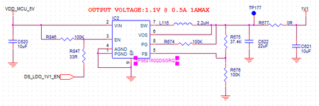
I am using TPS62160QDSGRQ1 in my design. I need to enable and disable it using a microcontroller GPIO and it voltage is 1.8V.
Below is my circuit.

1708491031182.png


My design calculations are are given below.

1708491092276.png


May I know your comments
 

Attachments

  • 1708491044448.png
    1708491044448.png
    13.8 KB · Views: 35
So what happens to your 1.8V uC when you've got an output tied to 5V through a resistor?
You're assuming your GPIO can sink current when it's output is high; not likely.
 
Okay good point. Will connect 100K from enable to Ground and microcontroller to other end of 100K
Hope that is fine.Below is my new circuit.

1708494778872.png

  1. Do I need to connect 100K to GND or 10K is enough
  2. How do I design this pull down resistor
 
Last edited:
Hi,

To calculate for the extreme values:
you missed some informations of the regulator datasheet:
* V_IH >= 0.9V (up to V_IN)
* V_IL <= 0.3V (down to GND)
* Internal Pulldown of 400 kOhms


Also from the microcontroller datasheeet:
V_OH ??? (min)
V_OL ??? (max)

When a device is powered with VCC (and GND) the levels at the IO do not go to these very rails. There always is a gap. How much we don´t know. (you should know)
They might be close to the rails. But not necessarily.
As an example - "TTL family devices" are supplied with 5V but V_OH / V_OL are specified with about 2.4V / 0.4V respectively.

***
I´m a bit confused.
It says "VDD_MCU_5V" ... this implies that the MCU supply voltage is 5V
On the other hand you say the ENABLE is controlled by an MCU pin with 1.8V. This implies that the MCU is supplied with 1.8V.
--> what is true now? (a simple sketch including MCU type, MCU_supply could clarify all worries)

Also "5V" are not 5.000V. Popular LM7805 for example has an initial tolerance of +/-4% which gives a range of 4.8V ... 5.2V

***
As long as there is no need (like very low quiescent current) you don´t calculate to the very limits. You just "overdrive" the pin (within it´s recommended operating limits).

So the simplest solution I see is to directly drive the EN signal with the microcontroller signal. I don´t even see the need for a resistor.
(But maybe I miss some important informations about what you intend to do and the microcontroller IO levels)

--> What problem do you see when driving the EN pin directly from the microcontroller pin?

Klaus
 
I´m a bit confused.
It says "VDD_MCU_5V" ... this implies that the MCU supply voltage is 5V
On the other hand you say the ENABLE is controlled by an MCU pin with 1.8V. This implies that the MCU is supplied with 1.8V.
--> what is true now? (a simple sketch including MCU type, MCU_supply could clarify all worries)
VDD_MCU_5V is a 5V supply coming from a switcher.
I have two MCUs in the board one with is working at 5V and other at 1.8V
1.8V MCU is used for enabling or disabling the switcher shown here

V_OH ??? (min)
V_OL ??? (max)
1.35V ,
1.8V

What problem do you see when driving the EN pin directly from the microcontroller pin?
Not tested yet.This is my first proto.So thought of providing options
 
Last edited:
Consider pulling EN to ground through an NPN transistor. That allows EN to be as high as the existing components allow and go to VCEsat when low. All you have to do is provide enough base current to drive the transistor. Using 100K pull-up (beware of the internal pull-down!) you only need to supply a few uA base current.

Brian.
 
Hi,

1.35V ,
1.8V
makes no sense! neither one for V_OL
Why is it so hard to give a link to a datasheet? or at least show the datasheet page (as PDF or screenshot PNG)

******
Not tested yet.This is my first proto.So thought of providing options
I´m not talking about "test", I´m talking about worries.
(No need to test either: If the MCU output delivers <0.3V / >0.9V it HAS TO work.)

Which options? Don´t provide riddles.

Klaus
 
Sorry my mistake.
V_OH ??? (min) = 1.35V
V_OL ??? (max) = 0.45V

I won't be able to share the datasheet because of NDA

--- Updated ---

Consider pulling EN to ground through an NPN transistor. That allows EN to be as high as the existing components allow and go to VCEsat when low. All you have to do is provide enough base current to drive the transistor. Using 100K pull-up (beware of the internal pull-down!) you only need to supply a few uA base current
In this case by default IC will be on and when you turn on the NPN transistor the IC will be off.Please correct me if I am wrong
 
Last edited:
V_OH ??? (min) = 1.35V
V_OL ??? (max) = 0.45V
we don´t get the datasheet. Thus we have to rely on you and your informations.

We can´t know if these voltages apply for your application. We don´t know the MCU´s test conditions (pin current, temperature, supply voltage) ... whether they are for unloaded or fully loaded pin.

If you want good answers you need to provide good informations first.

Klaus
 
Your 100K's would leave pin susceptible to noise coupling thru stray C,
10K more appropriate.

Any power sequencing chance that 1.8V processor comes up late after the
switcher's input power ? Typical there is a no mans zone when its outputs
invalid, so switcher input power should come up later or you will potentially
get unpredictable behaviour. Typical of todays processors as their power is
ramping up the outputs pass thru "no mans land" then default into hi-z inputs
until code takes over.

In short you want the enable input of switcher, if powered, not to be indeterminate
any time the control processor is starting up.

Particularly important if this is a life support application.


Regards, Dana.
 
Last edited:
In this case by default IC will be on and when you turn on the NPN transistor the IC will be off.Please correct me if I am wrong
Yes, but your MCU output is presumably software controlled so it should be a simple fix to reverse the logic or alternatively, you can use a second transistor as an inverter or an open collector inverter gate.

Brian.
 
Hi,

I reliable microcontroller system should have a reliable /RESET signal.

So you are free to pull the EN pin to /RESET instead of +5V.
You are free to add RC to create additional delay, and you may add a diode to speed up in one direction (falling or rising /RESET)

You may/can do anything. .. because you have the informations what is important for your application.
But we do not, so don´t expect us to have a crystal ball.

Better give all requirements .. then we know about them .. and we can help you to fulfill them.

Btw: even your ciruit has a pull up at EN .. and thus is ON per default.

Klaus
 

LaTeX Commands Quick-Menu:

Part and Inventory Search

Welcome to EDABoard.com

Sponsor

Back
Top