Continue to Site

Welcome to EDAboard.com

Welcome to our site! EDAboard.com is an international Electronics Discussion Forum focused on EDA software, circuits, schematics, books, theory, papers, asic, pld, 8051, DSP, Network, RF, Analog Design, PCB, Service Manuals... and a whole lot more! To participate you need to register. Registration is free. Click here to register now.

double volt-ampermeter with pic

Status
Not open for further replies.
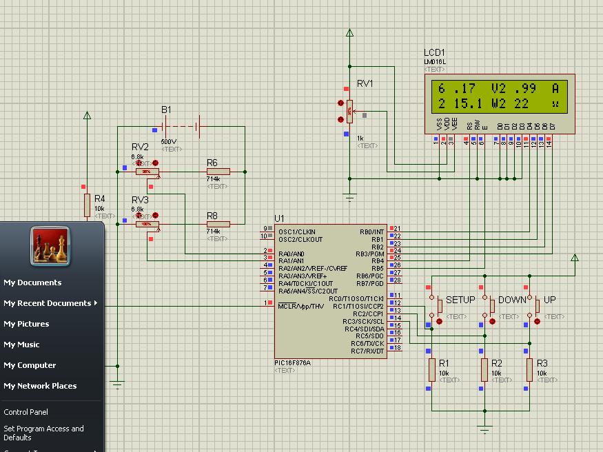
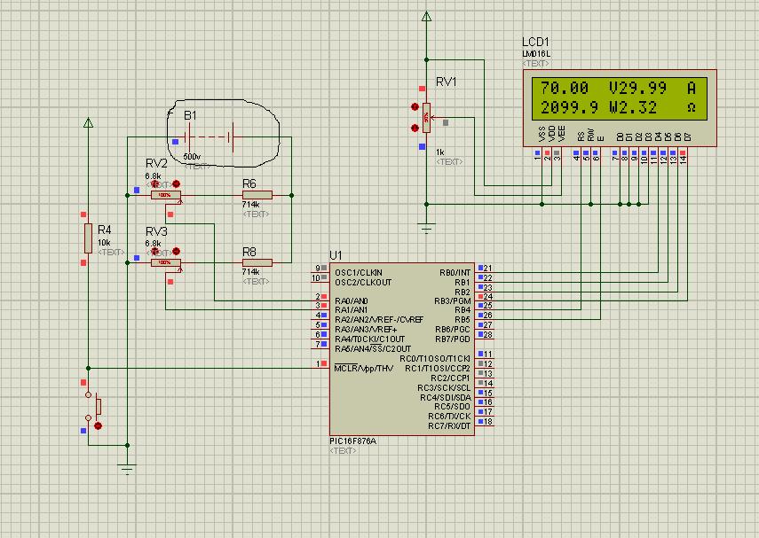
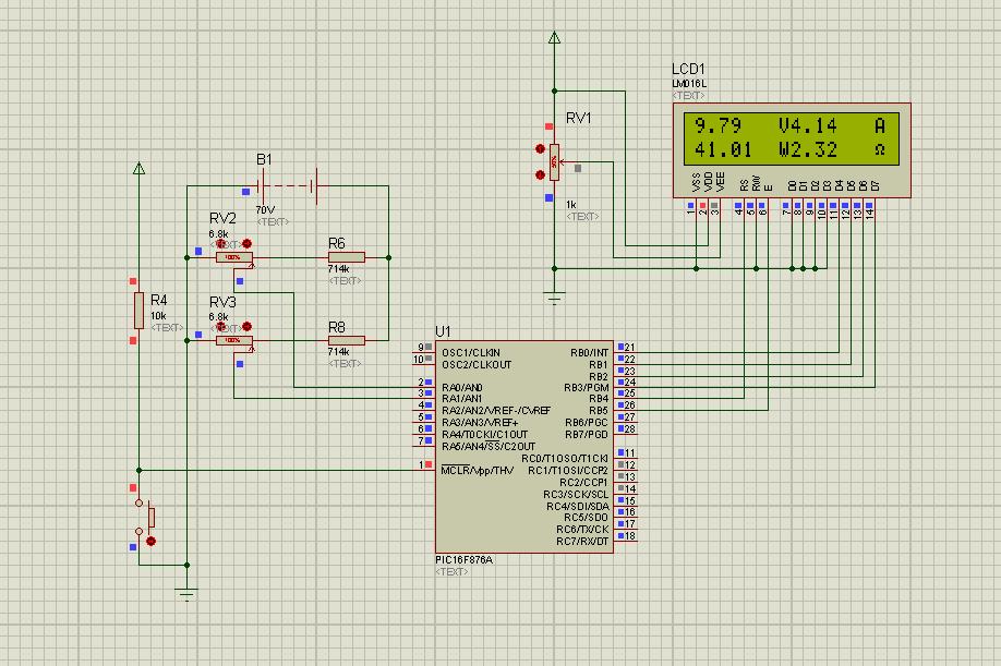
The shunt rezistor is put in series with the load. so gnd from left is not the same gnd from right. you check me? But what if ai make only one set of input circuit, only one for 500v and 50A. because with this range i can measure all kind of power right?
 

Check this. Press the buttons. Only two buttons are programmed.

- - - Updated - - -

Yes you can make like that, but chect the file I sent in last post. vlad3.rar

You ask Electronics DIY.com about the correct circuit.
 

Attachments

  • vlad3.rar
    18.8 KB · Views: 96

thank`s for all you`re time. i thinks is good no? so when i start it this VA meter the display is emphy. he wait my comand, when i push the down he is go to measure to range up to 70v right? and when i push the setup buton he is going to measure on range up to 500 right? correct me if i wrong.
 

Check this... Let me know if you need any changes. Check the hex file with the real hardmare. tell me if it is giving the right values.
 

Attachments

  • vlad5.rar
    18.3 KB · Views: 106
Last edited:

Thanks`s a lot man. i will let this input circuit because is work prety good. and these days i will make it. Have a nice evening, and sorry for my questions!
 

i thinks the some letters are hidden. if you can write a hex for 70v and 50A is verry good. But when you have time. Because i will make 2 of this one for 500V and one for 70V and i want to start alone without pushing buttons. Regards.
 

Attachments

  • dadadadwerwewe.JPG
    dadadadwerwewe.JPG
    103 KB · Views: 83

I can do it tomorrow. Just tell the V and A for the two projects. 500 * 50 = 25000.0 W. I think you will need more space to display P and Ohns. Can you use 20X2 LCD?
 
Last edited:

Oke, for the first project will be 70V and 30A this is priority, and i think is good a 2x16 LCD
and for the lastest i will use 20x2 LCD and will be 500 V and 50A, but this i will make in septembre.
 

OK. I will do the first one tomorrow. My mikroC is creating wrong hex files. I have to check it first.

-----Update------------

OK. I fixed mikroC. I will do your project tomorrow.

Check the attached file. It is for 70V and 30 Amps
 

Attachments

  • vlad7.rar
    18.7 KB · Views: 98
Last edited:

Have a nice day and thanks! I think I will change the start up mesage to `Hello handsome!` because maybe somebody will want this project and he will take it from this thread.

- - - Updated - - -

it`s something wrong with the last code push butons are not work
 

Check this . I have removed the buttons and I have written the code for 70 V and 30 Amps.
 

Attachments

  • vlad8.rar
    18.2 KB · Views: 108

Hey, but the the voltaje of battery is 500v?

I would class that has a poor deisgn, Protues is ok but when you come to real life testing you might get more than 5V input of the pic pins, To measure 500V you would need one good divider and looking at the pic the pots are set max but reading on the pic is only showing 70V ?????.
You could do an add on for the orginal by using a 4066 chip and swtich differnet values in for higher voltage I'd seen this in a fluke meter design which you can't get better than a fluke meter
 

Yes. I have sent you the proteus .dsn file. Change the value of battery to 70V.
 

I change that. take a look.

What is the actual voltage going onto pic when it's set for 70V, Becsaue ISIS will dispaly the voltage even though there might be 10V on the pin,

if it was me personally I would not use a vairable resistor to calibrate the voltage reading has some pots are bewteen 10-20% tollarance I aslo would use the same way in pic below then just calibrate through software you could even add a mosfet with extra resistor to switch in when higher voltage to gain more accuracy at the higher end of the voltage, Your hedaing in the right direction
v-div.JPG
 

Hey Vlad may i have the diagram and source file plz
 

Status
Not open for further replies.

Similar threads

Part and Inventory Search

Welcome to EDABoard.com

Sponsor

Back
Top