Continue to Site

Welcome to EDAboard.com

Welcome to our site! EDAboard.com is an international Electronics Discussion Forum focused on EDA software, circuits, schematics, books, theory, papers, asic, pld, 8051, DSP, Network, RF, Analog Design, PCB, Service Manuals... and a whole lot more! To participate you need to register. Registration is free. Click here to register now.

[PIC] I2C with pic18f4550

jerryd

Member level 2
Joined
Feb 4, 2013
Messages
48
Helped
0
Reputation
0
Reaction score
0
Trophy points
1,286
Activity points
1,709
Micro forum,

MS Windows, MPLAB X v6.05, XC8 v2.41, PIC18f4550

I'm trying to establish I2C communications between the pic and an MPU6050 Accelerometer and Gyroscope Sensor.

I have read both data sheets and everything I could read and copy on the internet that applies to I2C and these devices.

All I'm trying to do is send the address of the PMU6050(0xD0) and see if there is an Acknowledgement(ACK).

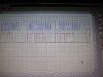
I run the code in my main.c and display the results(ACKSTST) on my 7 segment display. The value is always 0 even if I try to make it fail by taking the PMU out of the fixture.

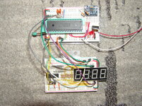
I have attached a photo of my test fixture and the code.

Any suggestions?

Code:

Code:
/* I2Cmain.c */
 
#include "config.h"

void I2C_Init()
{
 TRISB0=1;  // Set up I2C lines by setting as input
 TRISB1=1;
 SSPSTAT=0x80;  // Slew rate disabled, other bits are cleared
 SSPCON1=0x28; // Enable SSP port for I2C Master mode, clock = FOSC / (4 * (SSPADD+1))
 SSPCON2=0;
 SSPADD = 20000000 / (4 * 100000 + 1);  // Clock @ 100 kHz
 SSPIE=1;  // Enable SSPIF interrupt
 SSPIF=0;
} // end void I2C_Init()


void I2C_Ready()
{
 while(BCLIF); // Wait if bit collision interrupt flag is set

 // Wait for Buffer full and read write flag
 while(SSPSTATbits.BF || (SSPSTATbits.R_nW));
 SSPIF=0;    // Clear SSPIF interrupt flag
} // end void I2C_Ready()


char I2C_Write(unsigned char data)
{
 SSPBUF=data; // Write data to SSPBUF
 I2C_Ready();
 if(ACKSTAT) // Check for acknowledge bit
  return 1;
 else
  return 2;
} // end char I2C_Write(unsigned char data)


char I2C_Start(char slave_write_address)
{
 SSPCON2bits.SEN=1;      // Send start pulse
 while(SSPCON2bits.SEN); // Wait for completion of start pulse
 SSPIF=0;
 if(!SSPSTATbits.S)      // Check whether START detected last
 {return 0;}            // Return 0 to indicate start failed
 return (I2C_Write(0xD0)); // Write slave device address with write
} // end char I2C_Start(char slave_write_address)


char I2C_Stop()
{
 I2C_Ready();
 PEN=1;        // Stop communication
 while(PEN){;} // Wait for end of stop pulse
 SSPIF = 0;
 if(!SSPSTATbits.P) // Check whether STOP is detected last
 {
  return 0;   // If not return 0 to indicate start failed
 }
 return 0x01;
} // end char I2C_Stop()


// main function
void main(void)
{
 int x;
 HWsetup();

 I2C_Init();
 I2C_Start(0xD0);
 if(ACKSTAT)
 { x = 0; }else{ x = 1; }
 I2C_Stop();
here:
 displayValue(x);
 goto here;
} // end void main(void)


void HWsetup(void)
{

 TRISA  = 0x00;
 PORTA  = 0x00;
 
 TRISB  = 0b00000011;
 PORTB  = 0x00;

 INTCON2bits.RBPU = 0;
 
 TRISC = 0x00;
 PORTC = 0x00;
 
 TRISD = 0x00;
 PORTD = 0x00;
 
} // end HWsetup()

jerryd
 

Attachments

  • P1010343.JPG
    P1010343.JPG
    836.8 KB · Views: 41
Last edited by a moderator:
10K is higher than recommended for i2C pull-up resistance but check the address of the sensor is correct. I can't run the code at the moment but from my memory the address of the sensor isn't right.

See section 9.2 of the data sheet, alternative addresses can be selected.

Brian.
 
Brian,
Thanks for the reply.
Since I took that photo I have replaced those 10k pullups with 4.7k.

Everything I've read says the address of the MPU6050 is 0xD0. I'll look again.

If you plan to run the code I could post my config.h. I use an external 20mhz crystal.

Jerry
 
As always, addressing for I2C is a bit tricky. The data sheet for the MPU-6050(I used https://core-electronics.com.au/attachments/localcontent/MPU-6050_DataSheet_V34_14872bbfb20.pdf) does show the address as '0x110100X' (where X is controlled by the 'AD0' pin) (Section 9.2).
That makes it 0x68 or 0x69.
However I2C also adds a bit on the end to indicate if it is a read or write transaction - 1 telling the slave device to receive and 0 telling the slave device to send.
As stated in the PIC18F4550 data sheet (I looked at https://ww1.microchip.com/downloads/en/devicedoc/39632e.pdf) section 19.4.6.1, the first address needs to have the last bit set to 1 to tell the slave device to use the address and get ready to read the command that will come next.
Therefore try setting the parameter to the '!2C_Start()' function to 0xD1. (By the way, I also see that you ignore the parameter in that function and hard-code the wrong address - this is confusing and you should use one or the other.)
Susan
 
Susan,
Thanks for the info.
I have tried 0xD1 and just did again with the same results. Also fixed the addressing in the I2C_Start() function. At some point I tried 68/69.

As you can probably tell I'm stumbling around with something that I don't yet completely understand, ergo the request for help.

The one thing I haven't done yet is replace the MPU6050. I have a spare but as fate would have it my soldering iron died recently and I'm getting a new one tomorrow. I'll post the results.

Jerry
 
Hi,

use a scope to see what´s going on at the bus. Two channels at once.

***
You say Ack is 0. 0 on the bus (for ACK) means the address is acknowledged by the device.
This is impossible if the device is not connected to the bus at all. (your test)

If this is ture, then there are only a couple of possible reasosns:
* an SCL problem
* SDA is shorted to GND
* SDA pin of the microrcontroller is killed
* erroneous software

Klaus

Added: when posting code, use the CODE tags. Simplest way: just press the [ CODE ] button ..
--- Updated ---

Hi,

I´ve spent time on your code:

*****
please use
////
#define addrACCEL_R 0xD1 // or similar as Addres to READ from your accelerometer (LSB is set!!!)
#define addrACCEL_W 0xD0 // or similar as Addres to WRITE to your accelerometer (LSB is cleared!!!)
#define ACK 0
#define nACK 1
////
************
in your code you hard coded the slave address ... and this even twice, in a way that makes
(main) I2C_Start(0xD0); useless
since it is overruled by
(I2C_Start): return (I2C_Write(0xD0));

the above line should be corrected to:
(I2C_Start): return (I2C_Write(slave_address));
mind that I even changed the variable name, since at this placethe address may be for WRITE as well as READ access.
For sure the names need to be adjusted in all of the (I2C_Start) code.

****
Did you read and follow: http://ww1.microchip.com/downloads/...ed_With_I2C_Using_MSSP_on PIC18_90003281A.pdf
My recommendation: rely on the manufacturer sources, many random internet sources are not relaible at all.

There are several problems with your code like: (Mind I´ve no experience with MPLAB, so maybe my comments are not true for MPLAB)
* not using available libraries/functions
* when cheching the ACK, you just give the bit name, but not the register name: doesn´t it need to be "if SSP1CON2bits.ACKSTAT"
* don´t use return codes 1 and 2 only. Use 0 for the standard (non error) return code. Mind: FALSE = 0, TRUE is anything else. Thus 1 as well as 2 result in TRUE.
...many other problems.
--> Clean up your code, test it and .. in case .. repost it

****

here: (I2C_Write)
////
if(ACKSTAT) // Check for acknowledge bit
return 1;
else
return 2;
////
better just use:
///
return SSP1CON2bits.ACKSTAT;
///


**************
Here (main)
I2C_Start(0xD0); #-> I2C provides a return code. If not used better write "dummy = I2C_Start(..." , but in your case why not "x = I2C_Start(..."? it saves alot of code lines
if(ACKSTAT)
{ x = 0; }else{ x = 1; }
I2C_Stop();
here:
displayValue(x);

******
I2C in general:
Mind that you can READ data from a slave or WRITE data to a slave.
But in any case the master needs to SEND the address to the bus (with the LSB =1 for READ while the LSB = 0 for WRITE)
and in case of a slave_READ the master needs to RECEIVE data from the bus.

Don´t confuse WRITE with SEND and READ with RECEIVE.. to more clarify:
read them as
* bus_SEND (master sends a byte (address, data) to the bus)
* bus_RECEIVE (master receives a byte ... sent by the slave)
* slave_WRITE (master transmits informtions to a slave, like setting a new DAC value)
* slave_READ (master gets information form the slave, like getting a new ADC value)

this means your function "I2C_Write" is not a true "WRITE" function , but a SEND function.

Klaus
 
Last edited:
In your main function, you're checking for the ACK status immediately after calling I2C_Start(0xD0). However, as mentioned earlier, you should wait for the acknowledgment within the I2C_Start function itself.
  • Modify the I2C_Start function to wait for the acknowledgment after sending the slave address.
  • Handle the acknowledgment within the I2C_Start function and return the appropriate status.
  • Modify your main function to properly handle the return value of I2C_Start and act accordingly.
By the way, you can try to make pinguino with https://www.pcbway.com/project/shareproject/Pinguino_PIC18F4550.html
This is an Arduino-compatible board made with PIC18F4550.
 
eadboard,
Ask a question on this forum and you get many excellent suggestions/answers.

I made most of the updates suggested by Klaus. I also cleaned up some things that I had put in just for debugging. Now if there is no ACK returned from the slave the program will display a 1 as it should.

I have installed a new MPU6050 and new pic18f4550 but neither made any difference.

I don't have much of a scope. It's a DPSscope which is just a box with the probes that connects to my laptop through the usb port. Of course there's no storage capability. I put my I2C_Start(addrACCEL_W) and the I2C_Stop() in a loop and observed SCL and SDA. The top trace is the clock and the bottom trace is the address. This is about the best I can do with my scope. If the scope is to be believed it appears that on the 8th clock the address line is low(Write) and on the 9th clock it stays low which should mean an acknowledge. Hope you can expand the scope shot.

If I change the Start to I2C_Start(addrACCEL_R) there are no traces on the scope during the loop?

Still stuck.
Thanks to all who responded.
Jerry

[ CODE ]
Code:
/* I2Cmain.c */
 
#include "config.h"

#define addrACCEL_R 0xD1 // Address to READ from your accelerometer
#define addrACCEL_W 0xD0 // Address to WRITE to your accelerometer
#define ACK 0
#define nACK 1
#define _XTAL_FREQ 20000000
 
void HWsetup(void);

void I2C_Init()
{
 TRISB0=1;  // Set up I2C lines by setting as input
 TRISB1=1;
 SSPSTAT=0x80;  // Slew rate disabled, other bits are cleared
 SSPCON1=0x28; // Enable SSP port for I2C Master mode, clock = FOSC / (4 * (SSPADD+1))
 SSPCON2=0;
 SSPADD = 20000000 / (4 * (100000+1));  // Clock @ 100 kHz
 SSPIE=1;  // Enable SSPIF interrupt
 SSPIF=0;
} // end void I2C_Init()

void I2C_Wait()
{
  while ((SSPSTAT & 0x04) || (SSPCON2 & 0x1F));
}

void I2C_Ready()
{
 while(BCLIF); // Wait if bit collision interrupt flag is set

 // Wait for Buffer full and read write flag
 while(SSPSTATbits.BF || (SSPSTATbits.R_nW));
 SSPIF=0;    // Clear SSPIF interrupt flag
} // end void I2C_Ready()

char I2C_Write(unsigned char data)
{
 SSPBUF=data; // Write data to SSPBUF
 I2C_Ready();
 I2C_Wait();
 return (SSPCON2bits.ACKSTAT);
} // end char I2C_Write(unsigned char data)

char I2C_Start(char slave_write_address)
{
 SSPCON2bits.SEN=1;      // Send start pulse
 while(SSPCON2bits.SEN); // Wait for completion of start pulse
 SSPIF=0;
 if(!SSPSTATbits.S)      // Check whether START detected last
 {return 0;}             // Return 0 to indicate start failed
 return (I2C_Write(slave_write_address)); // Write slave device address with write
} // end char I2C_Start(char slave_write_address)

char I2C_Stop()
{
 I2C_Ready();
 PEN=1;        // Stop communication
 while(PEN){;} // Wait for end of stop pulse
 SSPIF = 0;
 if(!SSPSTATbits.P) // Check whether STOP is detected last
 {
  return 0x00;   // If not return 0 to indicate start failed
 }
 return 0x01;
} // end char I2C_Stop()

// main function
void main(void)
{
 int x;
 HWsetup();

 I2C_Init();
 x = I2C_Start(addrACCEL_W);
 I2C_Stop();
 
 here:
 displayValue(x);
 goto here;
} // end void main(void)

void HWsetup(void)
{

 TRISA  = 0x00;
 PORTA  = 0x00;
 
 TRISB  = 0b00000011;
 PORTB  = 0x00;

 TRISC = 0x00;
 PORTC = 0x00;
 
 TRISD = 0x00;
 PORTD = 0x00;
 
} // end HWsetup()
 

Attachments

  • P1010346.JPG
    P1010346.JPG
    842.4 KB · Views: 51
Last edited by a moderator:
Hi,

First things first:
I gave you a link to he MICROCHIP application note: MPLAB, I2C on PIC18 using MSSP.
This gives totally different code (examples) than I see on your code. Especially register access and bit access.
--> why is this the case? (I need this informationn, because I don´t have experience with MPLAB)

*

*********************
Scope picture
OK.

Something is wrong.

* Your code shows a single I2C access, then repeats to display "x".
* But the scope picture shows repeated I2C access
Where does this discrepancy come from? Do you get any compiling errors/warnings? If yes, show us.

*****
IF - you want to repeat the I2C process: please add a "small wait time" of a couple of milliseconds in I2C_IDLE before the I2C_Start. Not only that we can better see the IDLE condition (both lines HIGH) on the scope - but also for the I2C devices on the bus to see a clear START condition.
--> I can´t find the IDLE_to_START in your scope. It should be both lines HIGH, then a falling edge at SDA.
*****

Your code transmits address of "0xD0" which is 0b11010000, While one can see "1101" I can not see 4 times "0" in the scope at all.
This tells me: Either your scope picture does not match the code or the MSSP setup is wrong.

Now we have two issues where the scope picture does not match the code!!!
--> in case you show a scope picture of a different (modified) code .. then this is a waste of time! Don´t fool us.

*****
Coding:
return code "0" should always be the "normal", or the "good" state. Don´t use "0" to return an "error".

*****

Klaus
 

LaTeX Commands Quick-Menu:

Similar threads

Part and Inventory Search

Welcome to EDABoard.com

Sponsor

Back
Top