Continue to Site

Welcome to EDAboard.com

Welcome to our site! EDAboard.com is an international Electronics Discussion Forum focused on EDA software, circuits, schematics, books, theory, papers, asic, pld, 8051, DSP, Network, RF, Analog Design, PCB, Service Manuals... and a whole lot more! To participate you need to register. Registration is free. Click here to register now.

2.7 Volt in output pin.

R&DElec

Newbie level 5
Joined
Aug 1, 2023
Messages
10
Helped
0
Reputation
0
Reaction score
0
Trophy points
1
Activity points
79
Hello,
I am trying to program a PIC10F206 using pikit4+ MPLAB X IDE v6.05 and C8 compiler. I am super new in this field and I am facing a problem when I programmed the pic I only get 2.7 volt in my output pins. the program is super simple because I'm just trying to figure out why I am not receiving 5 volt at out put.
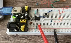
the pic is connected to 5v so pin2 is connected to 5v, pin 7 connected to ground, pin 8 connected to vdd MCLR(this was was suggested but it did not help), my pin 6 is GPO0 and is my input and pin 5 is my GPO1 my output and Pin4 GPO2 is my out put as well.
i also tried connecting an led and a 220 resistor at the outputss and then i used the multimeter to measure but nothing is helping


Code C - [expand]
1
2
3
4
5
6
7
8
9
10
11
12
13
14
15
16
17
18
19
20
21
22
23
24
25
26
27
28
29
#pragma config WDTE = OFF // Watchdog Timer (WDT disabled)
#pragma config CP = OFF // Code Protect (Code protection off)
#pragma config MCLRE = OFF // Master Clear Enable (GP3/MCLR pin function is digital I/O, MCLR internally tied to VDD)
 
#include <xc.h>
#define _XTAL_FREQ 4000000
 
void main(void) {
 
// Set GP0 as input and GP1 as output
TRIS = 0b1001; // GP1 as output and GP0 as input
 
while(1) {
 
// Check if GP0 is high
if(GPIObits.GP0) {
 
// Set GP1 high
GPIObits.GP1 = 1;
GPIObits.GP2 = 1;
} else {
 
// Set GP1 low
 
GPIObits.GP1 = 0;
GPIObits.GP2 = 0;
}
}
}


[ MODERATOR ACTION: Added 'C' Syntax tag ]
 
Last edited by a moderator:
Solution
Mystery solved!
On the 10F206 there is a comparator module which is turned on by default. When turned off it works as expected so you need to add the line:
CMCON0 = 0b01000001;
after the TRIS instruction, it should then work.

Curiously, XC8 locates the program at the end of memory, nothing wrong with that but it is more normal to start at zero and work towards the end.

Brian.
Hi,

First: show us your schematic. We need to see
* proper power supply bypass,
* how the input is connected
* how the output is connected.

Don´t use text.
Hand drawn schematic is O.K.
Photo is O.K (10kBytes should be enough) if every connecion is clearly visible.

****
Software:
( you use P2 as output but is not to be find in your comments.Update your comments.)
* Test: comment out the line "GPIObits.GP1 = 0"
* measure GP1 as well as GP2 voltage and report them to us.

Klaus
 
The program looks basically OK and the pins are also good, assuming you are using the 8-pin package.

What should happen is GP1 and GP2 should follow the logic state of GP0.

I can't prove it but I suspect two issues are at play. Firstly, getting 2.7V is technically impossible and I'm guessing you are measuring it with a testmeter rather than an oscilloscope. I think 2.7V is actually the pins rapidly changing from 0 to 5V and your meter is showing the approximate average. If you have not 'tied' GP0 to 0V or 5V with a pull-down or pull-up resistor it will pick up signals from nearby, most probably the other pins or mains at 50Hz or 60HZ and that frequency is what appears at the outputs. Try adding a 10K resistor between GP0 and ground so it adopts logic low state unless you connect it to 5V.

The other issue is unless you have a suitable decoupling capacitor across VSS and VDD very near to the PIC there will be unwanted signals on the supply. In particular, the internal oscillator may run erratically or not at all. I suggest adding two capacitors across the VSS and VDD pins, one an electrolytic of about 10uF and the other 100nF ceramic. Keep their wiring as short as possible and certainly no longer than about 20mm from the pins.

If those suggestions don't work, send us the schematic and photo as Klaus suggests.

Brian.
 
Thank you so much for being patient with my question. I tried to add the capacitors and the 10K resistor
 

Attachments

  • IMG_0544.jpg
    IMG_0544.jpg
    1.1 MB · Views: 62
Does it work now?
If not, try removing the wire linking MCLR to VDD because you have the MCLR function connected internally and that pin configured as a digital input.
Also, its worth checking that the + and - outputs from the power board are really linked together. It looks like there are different regulators for the outputs, you really should only use one power source even if they are set to the same voltage. If unsure, link the two + rails and link the two - rails across the sides of the board.

Brian.
 
no unfortunately Im still not getting any 5 v at out put, sometimes I even get 1.1 or even 0.9 V at output even with everything connected
 
pin 2= 5.1 v (this is vdd)
pin 3 = GP2 0.9 v
pin4 = GP1 1.1 v
pin5 = GP0 5.2v
pin6 = 0 (this is NA)
pin7 = is gnd
pin8 = 0 (MCLR is off )
 
Thank you. The voltages are certainly not correct.
I will compile your code and load it into a 10F206 tomorrow to see if I get the same results. I will be in hospital most of the day so it won't be until evening here.

Brian.
 
Hi,

respectfully. Either you changed the wiring (compared to the picture of post#4) or some of your measurement values are wrong.

Please verify verify the photo and the measurement values.

Klaus
 
yes the wiring is still the same I did not change it.. I just changed the chip because I tried to program different chip to see what goes wrong to see if the issue is the programming . Also Brian Thank you so ..the codes hat I tried so far are below:
#pragma config WDTE = OFF // Watchdog Timer (WDT disabled)
#pragma config CP = OFF // Code Protect (Code protection off)
#pragma config MCLRE = OFF // Master Clear Enable (GP3/MCLR pin fuction is digital I/O, MCLR internally tied to VDD)
#include <xc.h>

void main(void)
{
TRIS = 0b1101; // GP0 as input, GP1 as output

while(1) { // Infinite loop
// Check if GP0 is high
if(GPIObits.GP0) {
// Set GP1 high
GPIObits.GP1 = 1;
} else {
// Set GP1 low
GPIObits.GP1 = 0;
}
}
}
Or I even Tried to use code below, the only different is that it will also delay the output... but again not much difference:
#pragma config WDTE = OFF // Watchdog Timer (WDT disabled)
#pragma config CP = OFF // Code Protect (Code protection off)
#pragma config MCLRE = OFF // Master Clear Enable (GP3/MCLR pin fuction is digital I/O, MCLR internally tied to VDD)

#include <xc.h>
#define _XTAL_FREQ 4000000


void main(void) {
TRIS = 0b1101; // Set GP1 as output and GP0 as input

while(1) {
// Check if PIR sensor (GP0) is high
if(GPIObits.GP0) {
// Set (GP1) high
GPIObits.GP1 = 1;
// Start 5-minute timer
for(int i = 0; i < 300; i++) {
__delay_ms(1000); // 1-second delay
if(!GPIObits.GP0) {
break; // Exit loop if no motion detected
}
}

// If PIR sensor is still high, reset timer
if(GPIObits.GP0) {
continue;
}
} else {
// Set (GP1) low
GPIObits.GP1 = 0;
}
}
}
Again I am thankful so far I programmed few chip to make sure what is going wrong. the wiring is the same as above (the picture) again thank you so much
 
Does it work now?
If not, try removing the wire linking MCLR to VDD because you have the MCLR function connected internally and that pin configured as a digital input.
Also, its worth checking that the + and - outputs from the power board are really linked together. It looks like there are different regulators for the outputs, you really should only use one power source even if they are set to the same voltage. If unsure, link the two + rails and link the two - rails across the sides of the board.

Brian.
its because I disconnected it after this post so MCLR is not connected to vdd anymore
1691012545917.png
 
This was also another code that I tried to keep my output high enough so i can see what I can get ...
#include <xc.h>

#define _XTAL_FREQ 4000000
#define IN GP0
#define OUT GP1

void delay_5_min(void) {
for(int i = 0; i < 30; i++) { // 300 * 1 second = 5 min
__delay_ms(1000); // 1 second delay
}
}

void main(void) {
// Set IN as input and OUT as output
TRISGPIO = 0b01;

// Set OUT low by default
GPIO = 0b00;

while(1) {
// Check if IN is high
if(IN) {
// Set OUT high
OUT =1;

// Start 5 min timer
delay_5_min();

// Check if IN is still high
if(IN) {
// Reset 5-min timer
delay_5_min();
}
} else {
// Set OUT low
OUT = 0;
}
}
}
 
Mystery solved!
On the 10F206 there is a comparator module which is turned on by default. When turned off it works as expected so you need to add the line:
CMCON0 = 0b01000001;
after the TRIS instruction, it should then work.

Curiously, XC8 locates the program at the end of memory, nothing wrong with that but it is more normal to start at zero and work towards the end.

Brian.
 
  • Love
Reactions: R&DElec

    R&DElec

    Points: 2
    Thank you so much for patiently helping me to understand and learn how to program pic mcu..I always wanted to learn how to program one
Solution
Mystery solved!
On the 10F206 there is a comparator module which is turned on by default. When turned off it works as expected so you need to add the line:
CMCON0 = 0b01000001;
after the TRIS instruction, it should then work.

Curiously, XC8 locates the program at the end of memory, nothing wrong with that but it is more normal to start at zero and work towards the end.

Brian.
THANK YOU SO MUCH !!! IT WORKED.... I am so thankful. I really appreciate it.
image_67226113.JPG
image_67505665.JPG
 

LaTeX Commands Quick-Menu:

Similar threads

Part and Inventory Search

Welcome to EDABoard.com

Sponsor

Back
Top