Continue to Site

Welcome to EDAboard.com

Welcome to our site! EDAboard.com is an international Electronics Discussion Forum focused on EDA software, circuits, schematics, books, theory, papers, asic, pld, 8051, DSP, Network, RF, Analog Design, PCB, Service Manuals... and a whole lot more! To participate you need to register. Registration is free. Click here to register now.

AC main voltage measurement

Status
Not open for further replies.
then you shd go for some low output offset opamp, still the output will more linear and not exactly linear...
 

then you shd go for some low output offset opamp, still the output will more linear and not exactly linear...

can you plz suggest a circuit
 

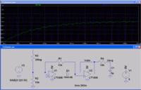
A single supply precision rectifier. LM358 could be used instead of LT1006 chosen for easy LTSpice simulation. There's a small (0.5 %) asymmetry that might be corrected by adjusting the resistor values (increase R2), it's below resistor tolerances for the present voltage divider ratio.

The low-pass time constant should be selected according to your ripple versus settling time requirement. A higher order active filter can be used for better performance.


For true RMS, you'll usually refer to available converter ICs. A classical log/antilog circuit with multiple OPs and monolithic transistor has been previously linked at edaboard. https://www.edaboard.com/threads/139198/

- - - Updated - - -

A new link for the LB-25 application note. www.ti.com/lit/an/snoa690/snoa690.pdf
 

Attachments

  • Fullwave.zip
    974 bytes · Views: 60

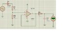
i have tried with diode, voltage divider circuit

ac-volt-measurement.JPG

the circuit gives stable output but from 235V AC i/p the multimeter gives values around 1.37V and became unstable. can anyone explain why its so and what should be done without making considerable changes in the circuit so as not to disturb the previous values..
 

I don't see a particular reason for "unstable" operation, except for 1N4007 leakage current.
 

I don't see a particular reason for "unstable" operation, except for 1N4007 leakage current.

how to make values stable...
 

the leakage current of diode should be Negligible as it is connected to AC main
 

the leakage current of diode should be Negligible as it is connected to AC main
Although I don't understand the specific conclusion, I think it's O.K. to make assumptions about likely and less likely reasons for unwanted circuit behaviour. The next step is to verify your assumptions. That's basically not difficult, but requires some measurements, e.g. with an oscilloscope. We can't do it from a distance.
 

Although I don't understand the specific conclusion, I think it's O.K. to make assumptions about likely and less likely reasons for unwanted circuit behaviour. The next step is to verify your assumptions. That's basically not difficult, but requires some measurements, e.g. with an oscilloscope. We can't do it from a distance.

the scope shows ripples about 40mV p-p
 

What is the output for 500V (Amplitude) ???

for 500V AC rms the input to controller is 1.9V but multimeter is not showing any variation in values but on oscilloscope the ripples are about 0.1V p-p

plz help
 

Change the R3 by 22k (in #65) the ripples will disappear but the reaction time will increase some how...
 

Change the R3 by 22k (in #65) the ripples will disappear but the reaction time will increase some how...

will this change previous values....
 

yeah slightly, The R and C at the end desires the ripples and response time. If you think the altered value is not enough for remove the ripples means use trial and error...
 

i dont have 2.2k so i used two 10k in series, it has increased the response time but also make the values at lower voltages unstable ....
 

for any case it would be 100ms so don worry about response time and slowly change the input and get readings. so this will work fine in real time..
 

for any case it would be 100ms so don worry about response time and slowly change the input and get readings. so this will work fine in real time..

but it didnt work as there are ripples
 

post the current using circuit...

the circuit is same as in #65 with only change is 10K is replaced by 20k resistor
 

for 500V AC rms the input to controller is 1.9V but multimeter is not showing any variation in values but on oscilloscope the ripples are about 0.1V p-p
but it didnt work as there are ripples
I hear some confusion in your statements. Any rectifier circuit has some ripple. If you calculate the expectable ripple for 470 ms averaging time constant, you'll get a ripple amount in the said range. In fact the circuit works as expectable.

There are several ways to get a stable measurement despite of the ripple:
- use a much longer time constant. Mostly impractical because the settling time after a voltage change becomes very long.
- use a higher order low-pass filter. You would need to learn a bit about active filters.
- average the measurement in the digital domain, ultimately over multiples of the mains period. 100 ms averaging time is used by most multimeters, works both for 50 and 60 Hz.
 

Status
Not open for further replies.

Part and Inventory Search

Welcome to EDABoard.com

Sponsor

Back
Top