Continue to Site

Welcome to EDAboard.com

Welcome to our site! EDAboard.com is an international Electronics Discussion Forum focused on EDA software, circuits, schematics, books, theory, papers, asic, pld, 8051, DSP, Network, RF, Analog Design, PCB, Service Manuals... and a whole lot more! To participate you need to register. Registration is free. Click here to register now.

AC main voltage measurement

Status
Not open for further replies.
why is you circuit unstable ? I had a similar problem with a 741 opamp in an industrial aplication ... since a i had no time to investigate the circuits to get the cause , i resolved the problem by software. I simply made 10 consecutive ADC measurements and compute the average value , so i made pretty good readings by three orders after coma. It is also recommended to check sampling time requirements of your adc (). I also added a 10 nF cap on the input pin, to put noise to ground. Also check the input pin's impedance to be conform to datasheet requirements .
 

The real problem is to define the formula for o/p of peak detector circuit at given i/p AC voltages that should be accurate for measuement purpose for that the o/p of circuit should be stable..
plz help its urgent
 

In practice, the measured peak voltage will never achieve the theoretical value of √2*Vrms because the mains voltage waveform is distorted by nonlinear loads like PC power supplies and motor inverters. In so far, measuring the peak value is the least accurate way to determine the mains voltage. Other methods have been suggested throughout this thread.

If you rely on the ideal sine waveform, or want to measure the peak value of an empirical waveform, the discussed OP peak detectors (with series resistor to achieve stability) will do it with acceptable error (< 1%). Although you can derive a "formula" for the deviation based on all circuit parameters, it's a rather long winded calculation. Most people would prefer either a simulation or more practical determine a calibration factor by comparing with a reference instrument.
 
  • Like
Reactions: tpetar

    tpetar

    Points: 2
    Helpful Answer Positive Rating
Negative input voltage is clipped by the OP input diodes. So you don't see the expected AC voltage with a multimeter.

the opamp i/p was in parallel not in series thus it must not be causing problem

i tried with only voltage divider consisting of two 1M ohm resistor and one 10K resistor, the AC voltage measured at 10K resistor is

0.33V at 60V AC i/p
0.377V at 70V
0.428V at 80V
0.471V at 90V
0.52V at 100V

why it is not following voltage divider formula...??
 

the opamp i/p was in parallel not in series thus it must not be causing problem
?????

why it is not following voltage divider formula...??
no idea what you're exactly doing.

This should be known:
- How are you generating variable AC voltage?
- How are you measuring the divider input and output voltage?
 

How are you generating variable AC voltage?

the variable ac voltage is generated from Variable Transformer.....

How are you measuring the divider input and output voltage?

i am using multimeter at output of Variable transformer that gives AC i/p voltages and across 10K ohm resistor

plz help urgently
 

There's no reason why the voltage divider shouldn't work correctly (as long as no other circuit is connected in parallel). So the problem refers to the performance of your multimeter and your measurement setup.
 

For accurate measurement always use good quality RMS measurement meter. Also Scope always help in such situation. Meter reading depend on many parameter.
 

Your readings look more or less linear is that not enough to measure a 500V??

0.377 / 70 * 100 = 0.538 you are getting 0.52, I believe after this 100V the curve will be more linear...
 

Your readings look more or less linear is that not enough to measure a 500V??

0.377 / 70 * 100 = 0.538 you are getting 0.52, I believe after this 100V the curve will be more linear...

0.538-0.52=0.018 it is a considerable difference for the precision and accuracy of 1V here are further readings ..

0.537V at 110V
0.588V at 120V
0.637V at 130V
0.688V at 140V
0.738V at 150V
0.783V at 160V


plz guide me the direction to proceed....
 

here are further readings
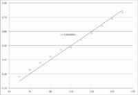
If you put the first and second series of measurements into a diagram, you'll notice a systematic offset that changes between both series. A QA engineer would take this as sufficient indication that your multimeter or another part of your setup is defective. (Or just the battery exhausted, whatsoever)

Obviously, further guessing from a distance becomes meaningless at this point.

- - - Updated - - -


Obviously, further guessing from a distance becomes meaningless at this point.

what should be done now....
 

If you put the first and second series of measurements into a diagram, you'll notice a systematic offset that changes between both series. A QA engineer would take this as sufficient indication that your multimeter or another part of your setup is defective. (Or just the battery exhausted, whatsoever)

Obviously, further guessing from a distance becomes meaningless at this point.

- - - Updated - - -


But both the readings shows more or less linear operation of the opamp (something changed in the surrounding)............

- - - Updated - - -

As instruments concern, Its does not means its linear or not.. It just means every time reads the same value or not. your circuit seems to be working take some long readings and create a lookup table or a function ( between 50 t0 100 0.05x, between 100 to 150 0.04x likes that) to go further if its bother you at the final concentrate on this....
 

But both the readings shows more or less linear operation of the opamp (something changed in the surrounding)............
As far as I understand, there's no opamp involved at this point, just a voltage divider and a multimeter.

"something changed" is the point, of course. In general terms, the accuracy of a measurement is limited by the involved error terms. A relative error of 5 % is a bit large.
 

so you use a transformer after all in your system ..... which is your ac main supply . Even autotransformers can saturate .... (i guess that the variable transformer you refer to is an autotransformer with cursor) I still suggest to use a low pass filter somewhere around the voltage divider . (EMI perturbations and harmonics affect all instruments.....)
 

can any one suggest a better design that can neglect these harmonics and distortions...

so you use a transformer after all in your system ..... which is your ac main supply . Even autotransformers can saturate .... (i guess that the variable transformer you refer to is an autotransformer with cursor) I still suggest to use a low pass filter somewhere around the voltage divider . (EMI perturbations and harmonics affect all instruments.....)

plz can u suggest where
 

As far as I understand, the transformer is a tool to generate a variable AC voltage for circuit test and calibration. Yes, it will produce certain (rather low) waveform distortion. Most likely the incoming mains voltage will already contain more harmonics than the transformer ever generates in regular operation. It's really a side problem.

A more interesting question would be about the intended operation mode of the AC voltage measurement. Unless you're specifically looking for peak value (I'm rather sure you don't) you would refer to rectified average or (ultimately) true RMS measurement. But I'm just repeating what has been suggested all the time.
 

so can anyone suggest circuit for true RMS measurement for accuracy even at 500V...
 

Status
Not open for further replies.

Part and Inventory Search

Welcome to EDABoard.com

Sponsor

Back
Top