Continue to Site

Welcome to EDAboard.com

Welcome to our site! EDAboard.com is an international Electronics Discussion Forum focused on EDA software, circuits, schematics, books, theory, papers, asic, pld, 8051, DSP, Network, RF, Analog Design, PCB, Service Manuals... and a whole lot more! To participate you need to register. Registration is free. Click here to register now.

AC main voltage measurement

Status
Not open for further replies.
What do you mean by "Unstable" . Is the third decimal point on your multimeter jumping around :0)

The circuit mentioned above works fine. With the values indicated , the circuit will give approx 1.6V out for 350Vac input.
There will be about 200mV P-P ripple on the 1.6V , but that is easily filtered out. You can do it in software or you can increase the cap value.
The problem with the second option is that it increases the time constant of the circuit. That may or may not be a problem for you.
Cheers
Neddie
 

If you put the filter capacitor with a value that will provide at least 4 time constants, the DC voltage WILL BE linear to the average of the main AC voltage.
 

thanks alot for the co-operation
plz can any one define the formula to determine the o/p volts of diode,voltage divider and capacitor circuit...
why the opamp based peak detector circuit is unstable even i replaced the capacitor with 1mf and 1.5mf ......the circuit works well in simulation but not in real time ......
plz help
 

Its a simple voltage divider.
Then, from the equivalent resistance of the divider, one calculates a capacitor which will provide a time constant at least 4 times larger than your period of 20 msecs.

Why it doesn't work? Either a defective component or an incorrect connection.
 

Its a simple voltage divider.
Then, from the equivalent resistance of the divider, one calculates a capacitor which will provide a time constant at least 4 times larger than your period of 20 msecs.

Why it doesn't work? Either a defective component or an incorrect connection.


plz drive the formula ....b/w i/p AC rms value and DC o/p voltage
 

plz can anyone define the formula to determine the output DC voltage at input AC rms of diode, voltage divider and capacitor cicruit....
 

I have tried with voltage divider and peak detector circuit. The voltages are correct in the simulation but not in real circuit.The voltage divider consists of one 10kohm and two of 1M ohm in practical circuit The resistances are 9.89Kohm and 2011k ohm total resistance and output voltage of voltage divider at 200V AC i/p is 0.803V it must be 0.98V
and output voltage of peak detector is

0.582v at 80v AC i/p
0.652V at 90v
0.723V at 100V
1.08v at 150v
2v at 160v
2.34V at 170v
2.5V at 180V
2.59V at 190V
2.66V at 200V


the o/p of opamp circuit become unstable
after 156V AC i/p. can any one describe the formula for
it...

plz help
 

?????????????????????plz help
 

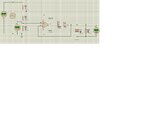
I presume the results in post #32 have been obtained with a specific circuit. But what is it?
 

Increase supply voltage temporary & see result if it is o/p voltage swing problem
 

AC voltage measurement1.JPG

PHP:
I have tried with voltage divider and peak detector circuit. The voltages are correct in the simulation but not in real circuit.The voltage divider consists of one 10kohm and two of 1M ohm in practical circuit The resistances are 9.89Kohm and 2011k ohm total resistance and output voltage of voltage divider at 200V AC i/p is 0.803V it must be 0.98V 
and output voltage of peak detector is 

0.582v at 80v	AC i/p 
0.652V at 90v
0.723V at 100V
1.08v at 150v
2v at 160v
2.34V at 170v
2.5V at 180V
2.59V at 190V
2.66V at 200V


the o/p of opamp circuit become unstable
after 156V AC i/p. can any one describe the formula for
it...


i am in need of a general formula that is valid for all i/p AC voltages
 

I previously stated
The circuit is unstable "by design", you'll need at least a small series resistor before the capacitor.
Before the capacitor means outside the feedback loop.

There's no useable "formula" for an unstable circuit.

output voltage of voltage divider at 200V AC i/p is 0.803V it must be 0.98V
Negative input voltage is clipped by the OP input diodes. So you don't see the expected AC voltage with a multimeter. Watch the voltage with an oscilloscope to see what happens.
 

There's no useable "formula" for an unstable circuit.

ofcourse after modifications and making circuit stable then formula can be generated accurately..


plz help
 

Status
Not open for further replies.

Part and Inventory Search

Welcome to EDABoard.com

Sponsor

Back
Top