Continue to Site

Welcome to EDAboard.com

Welcome to our site! EDAboard.com is an international Electronics Discussion Forum focused on EDA software, circuits, schematics, books, theory, papers, asic, pld, 8051, DSP, Network, RF, Analog Design, PCB, Service Manuals... and a whole lot more! To participate you need to register. Registration is free. Click here to register now.

mixer question, mixing a high and low freq component.

Status
Not open for further replies.

ltrlspree

Member level 2
Joined
Sep 24, 2008
Messages
49
Helped
9
Reputation
18
Reaction score
6
Trophy points
1,288
Location
Germany
Activity points
1,564
Hi there,

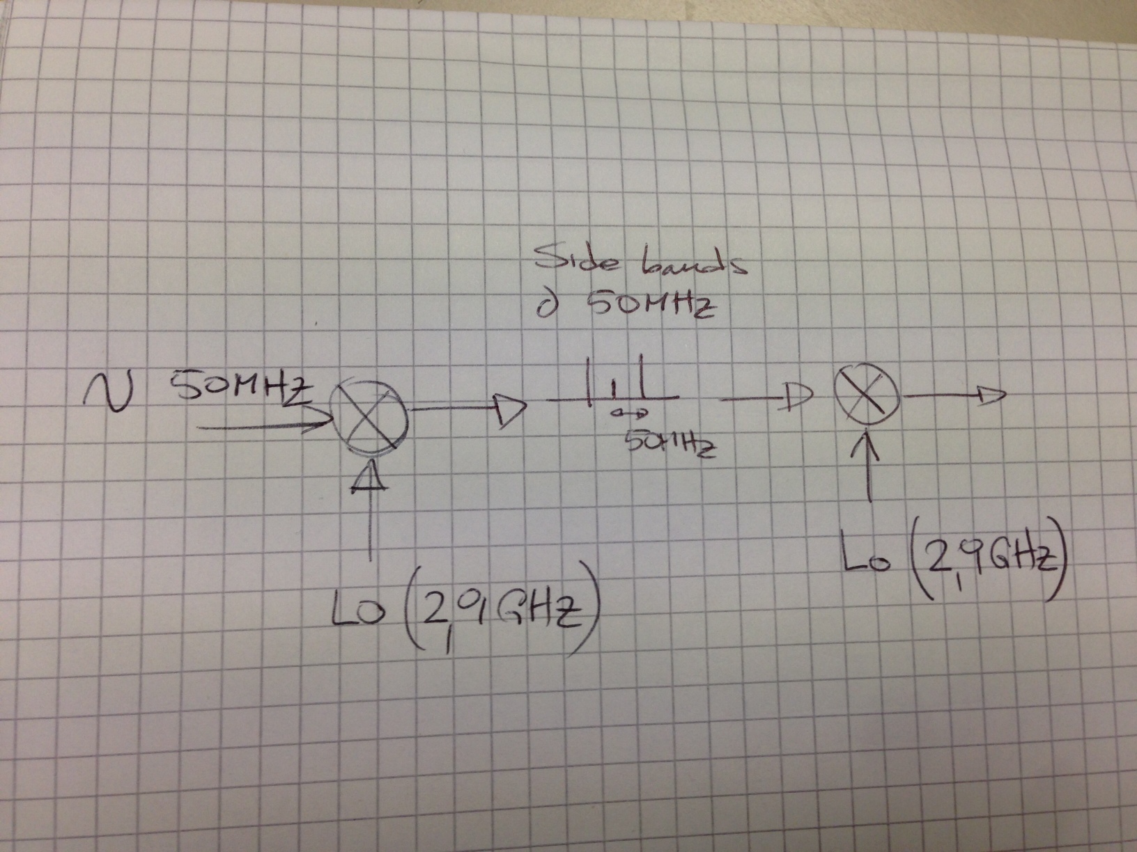
I am down converting with an active mixer a modulated signal at 2.9 GHz using an LO of the same frequency, the outcome should be in theory a sine of 50 MHz. (I know this was the original IF data)

On the bench I see this sine at the output of the mixer, but issue is I see a high level of AM modulation.....

I believe this to be a common issue while mixing two signals which are very far away from each other (50 MHz and 2.9 GHz)....could somebody point out some technical docs around this topic?

Thx
 

Mixing two signals with very different frequencies is no problem in a good mixer. For instance, mixers are used in "zero IF" receivers and Doppler radars without any problem.
Your "AM modulation" I guess can originate in unstable RF or LO, so the IF is not only 50 MHz you expect but other low frequency you do not. Check frequency stability of your signal generators, also if they are not AM modulated.
Often the AM component is 50 or 60 Hz due to poor DC power supplies...or the 2nd harmonic of it.
 

In additional to the comment above,
Check also LO driving signal amplitude to prevent self-mixing due to limited LO-RF isolation.If this amplitude becomes very high, LO mixes with itself at the RF input then it can generate a modulation by some phse shift.
 

I do not understand your question. Do you mean RF and LO are exactly the same frequency (or nearly so). If that is the case you have a beat note, the two frequencies are almost the same, and are generating an audio difference frequency as they add and subtract constructively.

If they are actually 50 MHz apart, you probably have something that is oscillating at a low frequency. Check your DC pins with an oscilloscope AC coupled. There should be nothing there slower than 50 MHz.
 

thx for the replies, so basically to give a clearer picture I am attaching an image.


Checking the output of the down converted signals with SA, instead of one tone at 50 MHz, what I see is two tones, centered at 50 MHz.
Distance between 50 MHz and each tone is approximately 600KHz.

I ll revise it with the provided comments, thx again.

br

If the unwanted peaks are 600 kHz apart, I would check cabling as 600 kHz may come from a local AM station, often high-power transmitter.
 

I believe I solved this, basically the two VCOs where delivering slightly different frequencies. By fine tunning the one at the downconversion side though its Vtune line, the two side bands consolidated into only one tone at the desired frequency.

br
 

I believe I solved this, basically the two VCOs where delivering slightly different frequencies. By fine tunning the one at the downconversion side though its Vtune line, the two side bands consolidated into only one tone at the desired frequency.

br

Congratulations!
 

Congratulations!

mmm unfortunately I was too optimistic, when I zoomed in the recovered signal at the downconversion side, I recognized it is AM modulated with a tone of approximately 250 Hz frequency and ~20 mVpp.


The fact that this is approx a multiple of 50 Hz is very suspicious.

At the 5v on the down converter I have two caps to ground, 10nF and 10 pH which should contain power supply variations in my opinion.

Any other idea is very welcomed.

BR

I would again advise to check by a scope all power supplies. Add 100 uF across all, check cables and signal sources. If you have a spectrum analyzer, you can use it to detect AM modulation on input signals. Some diodes are light sensitive and fluorescent lamps are used as noise microwave sources...
 

Status
Not open for further replies.

Part and Inventory Search

Welcome to EDABoard.com

Sponsor

Back
Top