Continue to Site

Welcome to EDAboard.com

Welcome to our site! EDAboard.com is an international Electronics Discussion Forum focused on EDA software, circuits, schematics, books, theory, papers, asic, pld, 8051, DSP, Network, RF, Analog Design, PCB, Service Manuals... and a whole lot more! To participate you need to register. Registration is free. Click here to register now.

Question about tank circuits

greenelephant

Newbie
Joined
Jan 18, 2021
Messages
1
Helped
0
Reputation
0
Reaction score
0
Trophy points
1
Activity points
13
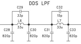
In reference to the three jpeg files attached, how can 3 tank circuits be modified to allow a lower limit of 100KHz? can the first one with capacitor c20 be modified to allow 100khz by changing c20 to 2500 picofarads? I appreciate everyones feedback?

juma--sch-1-136khz-lbp.jpg


juma--sch-1-dds-lbp.jpg


juma--sch-2-lbp.jpg
 

Attachments

  • juma--sch-1-dds-lbp.jpg
    juma--sch-1-dds-lbp.jpg
    42.8 KB · Views: 34
There's a standard formula for resonant frequency of LC network. It's governed by square root of LC. This means if you wish to reduce frequency to 50%, then you should increase C by 4x.
Or increase L by 4x.
Or increase both by 2x.
Or any suitable combination of multipliers in order to maintain desired rolloff curve (assuming your schematics are already properly designed).

The change should be done for all LC combinations that create resonance. It's hard to be sure exactly which LC cominations affect each other in your schematic

Note:
Greater L is associated with lower f, lesser Amperes.
Greater C is associated with lower f, greater A.

L&C ratio should be customized to accommodate the level of current in your circuit. If you wish to maximize power carried, then impedance matching is important.
 
The first circuit is a BPF, when the other two are LPF.
The BPF already have the lower -3dB cut-off frequency at 100kHz.
 
A tool to DIY filters :

Google "lc filter design utility"

A number of tools available.


Regards, Dana.
 

It must be hard to know how to specify a filter, if you are not sure what you need.

Then the best way to learn is to tell us what it is for and what your limitations are, ($, tolerances, etc). **

This online tool is awkward at first to use , but very interactive with sliders for some variables so you can tune it and see the response instantly for Ripple, LC Order (qty) , Freq and it assumes 50 ohm load Impedance, but you may change that easily. You may have to add Rs (source) if driving from an Op Amp or Transistor that matches the configuration and is realistic (assuming you are working << 1MHz)

But quickly I chose middle spectrum, 8 poles, Chebychev,, 100kHz, 15 kHz BW and low ripple but adequate rejection on skirts using ideal parts, which will affect performance. But voila. Then better tools might use real parts from a library. But 1st answer ** and specs.

1711376165758.png
 

LaTeX Commands Quick-Menu:

Part and Inventory Search

Welcome to EDABoard.com

Sponsor

Back
Top