revky
Newbie level 5
Hi,
I have a question about the best way to combine to short pulses with small amplitude to obtain a monocycle pulse.
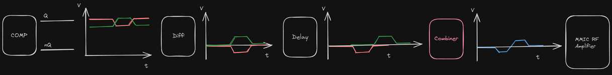
I am using a fast CML Comparator to generate short pulses (roughly 0.5 - 1nS) which i differentiate both complementary outputs to remove the DC part the and the positive edge i delay (using TL) by the pulse width in order to offset them. What is are some of the ways to recombine these pulses as I need to feed them into a MMIC amplifier?
Amplitude of these pulses is relatively small at this stage around 200-300mV
Many Thanks
I have a question about the best way to combine to short pulses with small amplitude to obtain a monocycle pulse.
I am using a fast CML Comparator to generate short pulses (roughly 0.5 - 1nS) which i differentiate both complementary outputs to remove the DC part the and the positive edge i delay (using TL) by the pulse width in order to offset them. What is are some of the ways to recombine these pulses as I need to feed them into a MMIC amplifier?
Amplitude of these pulses is relatively small at this stage around 200-300mV
Many Thanks
") Does it repeat ? What's it for?
Does it repeat ? What's it for?