Continue to Site

Welcome to EDAboard.com

Welcome to our site! EDAboard.com is an international Electronics Discussion Forum focused on EDA software, circuits, schematics, books, theory, papers, asic, pld, 8051, DSP, Network, RF, Analog Design, PCB, Service Manuals... and a whole lot more! To participate you need to register. Registration is free. Click here to register now.

Matching technique at high frequencies

guytoub

Full Member level 2
Joined
Dec 23, 2004
Messages
123
Helped
4
Reputation
8
Reaction score
5
Trophy points
1,298
Activity points
922
Hello,

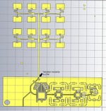
i wanted to know how is the best way to match a patch antenna array at high frequency like 24Ghz?
i know at this frequency lumped component don't work.
 
The only way to design a matching circuit is to use Microstrip Lines Matching. You can find many techniques in everywhere.
 
You should go step by step, and match the individual antennas first, by using the correct dimension for probe feed or inset feed.
There is not much need for additional matching if you also design the dividers properly.
 
Higher frequencies like 24 GHz are exactly the use case for which David Pozar developed the aperture-coupled patch antenna. A probe feed isn't really recommended due to tolerancing and the electrical sizes of the substrates used. There is no strict requirement to use microstrips -- and these are generally considered undesirable at mm-wave frequencies due to excessive loss/radiation.

Can you provide more information on your array design?
 
In my oppinion the best way to do it is to not use any impedance matching components at all, for patch antennas.
For individual patches I would go for a inset feed type topology, which (when is tuned) match the widest impedance range.
The first large patch array antennas, used this type of feed, without any matching components.
 
hello,
in my example I have a microstrip transition to a coplanar line. I removed everything that is components and on the line and I attack an RF amplifier. when designing my antenna network, I am well adapted but near my amplifier I would like to know how the adaptations are made if ever we have to make them.
@vfone @PlanarMetamaterials @BigBoss
 

Attachments

  • arrayy_24.png
    arrayy_24.png
    152.7 KB · Views: 37
If you refer to the transition from CPW to microstrip shown in the picture, this could be a Pi (C,L,C) matching network.
 

Attachments

  • pi.jpg
    pi.jpg
    17 KB · Views: 36

LaTeX Commands Quick-Menu:

Similar threads

Part and Inventory Search

Welcome to EDABoard.com

Sponsor

Back
Top