Continue to Site

Welcome to EDAboard.com

Welcome to our site! EDAboard.com is an international Electronics Discussion Forum focused on EDA software, circuits, schematics, books, theory, papers, asic, pld, 8051, DSP, Network, RF, Analog Design, PCB, Service Manuals... and a whole lot more! To participate you need to register. Registration is free. Click here to register now.

zener power supply circuit

Status
Not open for further replies.

david90

Advanced Member level 1
Joined
May 5, 2004
Messages
423
Helped
9
Reputation
18
Reaction score
4
Trophy points
1,298
Activity points
3,611
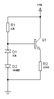
I put together a zener based ps that look like this
**broken link removed**

with Vz= 3.3V (200mw), Vs is 12-15VDC, current limit resistor = 200Ohm.

The problem that I having is when Vs= 15VDC, the output goes up to 4.5V. I have a very small load connected to the output.

Is there something wrong with my zener? I thought zener is always suppose to maintain a 3.3V voltage drop. My zener does get warm and my ammeter showed about 50mA of current.
 

When you apply 15V at the input the zener current is: Iz = (15-Vz)/200 = 52.5mA. The power dissipated by the zener is Pz = Iz Vz = 236mW. It will become hot and your limiting resistor wil too. This is the no load condition. I suspect you are using a small package diode. In this case you are above the shown 200mW spec. A more reasonable no load current should be about 20mA, so change the resistor value to 470R or 560R. Zener diodes are not so good to keep a constant voltage with large current swings. Bellow 20mA you can expect a variation of about 0.5V, depending on the current consumed by your load.
Regards
 

A low voltage zener is not a good voltage clamp. There is a current dependent resistor in series with the zener. The voltage across that resistor adds to the zener voltage.

Check the datasheets from some manufacturers. Some provide graphs for zener voltage versus zener current. When I look to the graph of a BZX-84-V (Vishay), at 40mA the voltage across the device is 4.0V. At 5mA it is 3.3V. Of course there is spread in the initial zener voltage and temperature drift.

If you only have a very small load, you may increase the current limiting resistor to reduce the current, this will reduce the actual zener voltage also. If you have both low and high current loads, a regulator IC will give you better voltage stability.

Thanks for the help.

Is there a way to protect my circuit in the event that the zener gets fried?
 

Hi,
You could have very small amount of current going through the zener and using this drive a transistor which drives the load, like:
77_1293436947.png

Alternately, you could use a 3.9v zener and avoid the diode which has been placed to compensate for the 0.6v drop of the transistor.

Hope this helps.
Tahmid.
 

What is your minimum and maximum load current, and what is the minimum and maximum voltage your application accepts?

The Voltage stabilisation of Tahmid's circuit is better and the power consumption is less. If you put a resistor in the collector, Tahmid's circuit is even short circuit proof (like the zener circuit). Off course you have to evaluate the power dissipation for the additional collector resistor and transistor. If your load current can reach almost zero, make sure you use some parallel resistor to keep the BE junction conducting.

Regarding protection. For the zener circuit, just put another zener in parallel. In case of an open failure, the other zener will take over the voltage regulation function. The disadvantage is that you don't know something is broken.

In general over voltage protection (due to malfunction) is often implemented with a so-called "crowbar circuit". It uses a thyristor in combination with a voltage comparator (for example a zener that drives the gate). When the voltage exceeds the safe level, the thyristor is fired and creates an almost short circuit. This short circuit condition should blow a fuse before the thyristor is fried.
 

Is there something wrong with my zener? I thought zener is always suppose to maintain a 3.3V voltage drop. My zener does get warm and my ammeter showed about 50mA of current.


Hi,

In my experience zener psu circuits are always problematic in both design and use.

With so many cheap voltage regulators on the market that have loads of protection built in, wonder if there is there a reason you are avoiding them.
 

your vs is 15 max so i = 15/200 = .075 A and the power consumption will be i2r that will be .075*.075*200 nearly 1.125 that means you will require 2 watts zener diode and 2 watts resistor for your design
 

your vs is 15 max so i = 15/200 = .075 A and the power consumption will be i2r that will be .075*.075*200 nearly 1.125 that means you will require 2 watts zener diode and 2 watts resistor for your design

This is not correct. The voltage across the resistor is the supply voltage less the zener voltage (4.5V as measured), so these power figures do not reflect the actual circuit. A zener diode submited to a power dissipation almost 5 times above its rating would be damaged quickly.
 

This is not correct. The voltage across the resistor is the supply voltage less the zener voltage (4.5V as measured), so these power figures do not reflect the actual circuit. A zener diode submited to a power dissipation almost 5 times above its rating would be damaged quickly.

sorry but can you briefly tell me about how to select zener diode watt capacity
 

Hi,tahmid has post the circute diagram that you can use it's more reliable.
 

sorry but can you briefly tell me about how to select zener diode watt capacity

The power dissipated by a zener diode is Pz = Vz x Iz. You should consider the maximum power which corresponds to the no-load condition, where Iz = (Vcc - Vz)/R, unless you can guarantee your circuit is always loading it. In this case you can subtract the minimum load current from the zener current. You have to consider how power will be dissipated. Usually, manufacturers show a derating curve based on lead lenght or pcb track width. Roughly speaking, choose a device with twice the power you have calculated, or in other words, keep it cool. And don´t forget: the power shown in the datasheet is maximum, not the one that guarantees a reliable operation.
 

The Voltage stabilisation of Tahmid's circuit is better and the power consumption is less.
stabilisation better - true, power consumption little bit bigger, but thats another story.
Why you don't use IC regulator?
 

Status
Not open for further replies.

Part and Inventory Search

Welcome to EDABoard.com

Sponsor

Back
Top