Continue to Site

Welcome to EDAboard.com

Welcome to our site! EDAboard.com is an international Electronics Discussion Forum focused on EDA software, circuits, schematics, books, theory, papers, asic, pld, 8051, DSP, Network, RF, Analog Design, PCB, Service Manuals... and a whole lot more! To participate you need to register. Registration is free. Click here to register now.

Xc Saves power when used as resistor ? True?

Status
Not open for further replies.

I_think

Member level 5
Joined
Dec 29, 2011
Messages
92
Helped
8
Reputation
16
Reaction score
7
Trophy points
1,288
Activity points
1,900
When we use capacitive drop power supply does it save power ? True?
New Project.jpg

The above way for reference.
 

Yes, it isn't a completely powerless dropper but far more efficient than a resistor in most cases. Substitute Xc for R to calculate the value you need.

Words of caution though:
1. The value of Xc depends on the frequency. Xc = 1/(2*pi*f*C).
2. If it fails short circuit the full voltage appears at the load.
3. Unless you have some DC present, you must use a non-polarized capacitor.
4. If you disconnect the source or the load, the capacitor might retain charge.
5. If you are using it as an AC line dropper it provides no isolation barrier could be extremely dangerous.
6. If you are using it as an Ac line dropper you must draw equally on positive and negative half cycles or it will simply charge up.

Brian.

Thanks for the reply Brian.

I have designed a few power supply using capacitive drop. And they are amazing and cost effective when you need low current.
I was trying to understand how efficient is this method compared to resistive ( using resistor). How much power can really be saved and wasted, any way to mathematically calculate it?
 

Only the ESR of the capacitor dissipates heat and typically it will only be a few Ohms. Consider it's overall resistance as Xc+ESR and you can use Ohms law to work out the anticipated losses. There may be other small losses in the capacitor but they are negligible.

Brian.
 
Yes, it isn't a completely powerless dropper...

An ideal capacitor does not dissipate any power. If there is a DC component present, that part will be blocked fully.

Most resistors fail as open circuit and so do some capacitors. I think capacitors used for PF corrections fail in the open circuit mode.

You can use a capacitor with AC input and a half wave rectifier; it will not be most efficient but it will work (because half wave rectified is equal to a DC plus AC and the capacitor will block the DC and pass the AC).

Let me say its conditional. If it is connected to the output of pulse transformer , It would work as you said. But if the half cycle is generated using diode in series, then there would be no discharge path.
 

This is point 6 I made in post #2.
I disagree that it will work in a conventional half wave rectification circuit, the capacitor would just charge up as though it was a reservoir. There has to be continuous current through the capacitor so if being used to produce DC, the rectifier has to be full-wave, ideally a bridge so it has equal 'push' and 'pull'.

Brian.
 

I disagree that it will work in a conventional half wave rectification circuit, ...

Just for fun, I just tried a simulation (310V AC in series with a 100R in series with a 1uF cap in series with a 10K resistor) and I see AC current flowing through the capacitor. Did I do some mistake?
 

Just for fun, I just tried a simulation (310V AC in series with a 100R in series with a 1uF cap in series with a 10K resistor) and I see AC current flowing through the capacitor. Did I do some mistake?

And how did you generate half wave? can you share the screenshot if the schematic ?
 

can you share the screenshot if the schematic...

Here it is: you can simulate it in any simulator of your choice:

Screenshot from 2019-05-06 10-08-42.png
 

Here it is: you can simulate it in any simulator of your choice:View attachment 152856

ok, Screenshot of result please. Also which simulator did you use?
- - - Updated - - -

ok, Screenshot of result please. Also which simulator did you use?

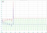
Graph.jpg

In the above attached graph you will see, Red line which shows that it takes time to charge the cap . But once when its charged , its steady.
In the blue graph , which is output (across load 10K) gradually becomes zero as the capacitor charges.


In your circuit try lowering the AC input voltage. The wrong results you get might be because of breakdown of component over voltage.
 

There are many variations on the capacitive dropper for low power auxilliary power supplies - however there are a few gotchas:

1) Use a high power safety resistor in series with the cap - esp on 230Vac - to limit current at power up - and for limiting current if a ripple control system is used in your area. e.g. for 230V 330 ohm will limit max inrush to 1A pk - and for 50mA it dissipates 825mW so use a 2W at least ...

2) make sure any zener limiting is up to the job - esp the pads on the pcb big enough to conduct away any heat.

good luck...
 

Please reconsider. A least one diode missing, as already explained by betwixt.

Sorry, my simulation was wrong. My apologies.
 

Status
Not open for further replies.

Similar threads

Part and Inventory Search

Welcome to EDABoard.com

Sponsor

Back
Top