Continue to Site

Welcome to EDAboard.com

Welcome to our site! EDAboard.com is an international Electronics Discussion Forum focused on EDA software, circuits, schematics, books, theory, papers, asic, pld, 8051, DSP, Network, RF, Analog Design, PCB, Service Manuals... and a whole lot more! To participate you need to register. Registration is free. Click here to register now.

Would timing tool check this path?

Status
Not open for further replies.

kaz1

Full Member level 6
Joined
Aug 15, 2019
Messages
322
Helped
18
Reputation
35
Reaction score
51
Trophy points
28
Location
UK
Activity points
1,921
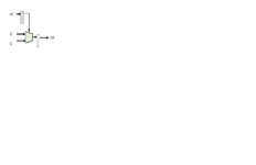
c1 and c2 are constants (wires).
sel selects one of them for output(out). There is timing path from sel register to out register but none from c1/c2 to out
How does Quartus or Vivado check the c1/c2 to out path since it is not a timing path by definition:

.


timing_path.png
 

Attachments

  • timing_path.png
    timing_path.png
    6.4 KB · Views: 146

Hi
How does Quartus or Vivado check the c1/c2 to out path
if you want C1 to OUT timing, then there should be a signal edge to refer the timing to.
But C1 as well as C2 are static, there is no edge, thus there is no meaninful timing to OUT.

The only meaningful timing is - like already writen: SEL to OUT.

Klaus
 

but physically c1/c2 to out is very relevant to pass timing.
C1/C2are static but not their output after selection. I could be clocking sel every clock and the delays from c1 or c2 may fail. C1/C2 could have bus skew at clock edge if multiple bits.
 
Last edited:

Timing analysis is assessing the actual gate level path, in this case from sel to out. You can sketch the path and calculate delay and skew. Presumedly, the exact timing values depend on the c1 and c2 signal levels. But as they are fixed, you get only one delay value for sel to out.

This is a combinational path, why to you refer to clocking?
 

sel is clocked, not c1/c2.
The clock edge will decide sel and hence sample either c1 or c2 buses. So their delay is relevant.
 

What do sou mean with "c1 or c2 buses"? May be your initial description is wrong. You said, c1 and c2 are constants (at compile time) thus eliminated in synthesis.
 

They are constants (multibits) yes but as sel will be going active for c1 or c2 at clock edge and one of them is selected. of course they are static but are not picked up as such immediately; they go through comb, paths to be passed to out. if sel can just pick them up instantly then there is no issue.
 

Hi,

You still are wrong. As long as C1 and C2 are static the timing only depends on SEL.
Only SEL controls the OUTput.

In other words:
Because C1 and C2 are static:
* SEL does not switch C1 or C1 to OUT anymore.
* SEL switches HIGH or LOW to OUT.

There is no: C1_rising to OUT_rising timing (as example).
There only is: SEL rising to OUT_rising.

Klaus
 

Hi,

there are only for possible combinations of C1 and C2:

C1=C2 = 0 --> OUT = 0, independent of SEL
C1=C2 = 1 --> OUT = 1, independent of SEL
C1=0, C2=1 --> OUT = SEL (SEL to OUT timing)
C1=1, C2=0 --> OUT = !SEL (SEL to OUT timing)

mind: on the right side of "-->" there never is C1 nor C2

Please look at the synthesis results.

Klaus
 
Last edited:

Thanks Klaus,

I think I can imagine your view now if we look at truth table e.g.

Code:
c1     c2    sel    out
0      1       0       0
0      1       1       1

so at implementation it will be one lut (for one bit case) with [c1-c2-sel] as 3 bit address and lut configured for [out] values. Thus I don't need to worry about c1/c2 as they are fixed.

To clear my thoughts further and putting it the other way, if I add register to c1 and c2 paths before mux and so create new timing path would that guarantee it will pass timing always no matter what. I think it depends on routing, doesn't it? or is it false path then.
 

If the input to the registers is constant, they are still eliminated in synthesis and thus c1 and c2 won't affect timing. You might enforce synthesis of the registers by synthesis attributes, but why would you do?
 

Hi,
so at implementation it will be one lut (for one bit case)
I doubt it even uses a LUT.
I guess it just gets reduced to simple logic cell where it uses either the straight input of SEL or the inverted input of SEL.
OUT = SEL or OUT = !SEL.

I expect the delay will be a single logic cell delay (SEL-OUT) plus routing.

Klaus
--- Updated ---

if I add register to c1 and c2 paths before mux and so create new timing path would that guarantee it will pass timing always no matter what.
Think about sending two parcels. Parcel "C1" and "parcel "C2".
It takes some time to deleliver them to the target office. There they are stored in two "registers".
In your case the "delivey time" to the target register takes max. 1 clock cycle after FPGA is READY.
But from this point on the delivery time does not matter anymore.

Now you go to the target post office.
There is a man (SEL) behind the counter. You ask him to get the parcel "C1".
It just matters how fast "SEL" can handle you the parcel.

***
Even if you use registers I guess the optimizer will recognize that the input is static and thus omit the registers.
(Maybe depends on optimizer setup)
In case it uses a LUT, then the LUT (depending on circuit) maybe takes 2 logic_delay_units or so.

There should be documents for timing:
* Logic_cell_input to output
* LUT_control input to output

Klaus
 
Last edited:

If the input to the registers is constant, they are still eliminated in synthesis and thus c1 and c2 won't affect timing. You might enforce synthesis of the registers by synthesis attributes, but why would you do?
if we apply reset process then c1/c2 would be implemented as registers.
I am asking because it may clear my thoughts. Having registers forces timing path by definition and then I expect tool to tell me something assuming it recognises the constants. In effect tool contributes to this thread.
 

Where would you apply the reset though?
If C1 and C2 are constant, then there is no reset in involved. They are static.
If C1 and C2 can change with a reset, then they are no longer static and hence no longer constant. And hence no longer match your original drawing.

@KlausST already pointed out in #11 that there are only two possible outputs when C1/2 are constant and different. Using registers changes the possible outputs.
Apply async reset at start only to force compiler to generate registers.
I have done that with filter coeffs a lot of times. you can declare filter coeffs directly as wires or insert them in clocked process with async reset applied. Try it and see and I expect registers will be implemented but obviously wasted. I applied zeros on them during reset then static constant values on first clock edge and thereafter. The registered output will be in effect static after reset release.
 

Hi,

in my eyes you overcomplicate things here. For sure we don´t know the whole background of the application.
If you apply an async RESET you also need to an additional signal to SET the register.

RESET usually is a global signal spread over the whole chip. Using "local" registers just increases effort and ressources.

--> If you like to apply a RESET, then why not at SEL or at OUT?

Klaus
 

@kaz1 Why do that? you're creating an extra route and input to the mux lut. Without them it can just pin the inputs to the constants at the mux lut directly. Its a waste of registers and routing.
 

@kaz1 Why do that? you're creating an extra route and input to the mux lut. Without them it can just pin the inputs to the constants at the mux lut directly. Its a waste of registers and routing.
That is what I said. I brought reset in discussion just for sake of understanding this thread issue but let us not get side tracked on that as it gets complicated comparison.

Let me rephrase my question as below figure :
c1 & c2 are now multibit constants. sel path to input D of output register passes timing. c1 & c2 alternate with sel as input to same register.
Away from tool versions and implementation platforms, if delay of transition of c1=> c2 ...etc is too late then design would go wrong.
You may say sel having passed timing protects against that but I don't see how as the paths from c1 or c2 to final bus at D input is undefined and are not part of sel timing path.

timing_path2.png
 
Last edited:

Status
Not open for further replies.

Part and Inventory Search

Welcome to EDABoard.com

Sponsor

Back
Top