Welcome to our site! EDAboard.com is an international Electronics Discussion Forum focused on EDA software, circuits, schematics, books, theory, papers, asic, pld, 8051, DSP, Network, RF, Analog Design, PCB, Service Manuals... and a whole lot more! To participate you need to register. Registration is free. Click here to register now.
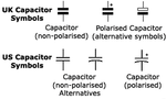
I disagree. Almost every American capacitor is drawn with a straight lead and a curved lead. If the capacitor is polarized then the straight lead has a "+" beside it. Some Brit people draw a rectangular box as the "+" lead and a straight line as the "-" lead.
...then i ask myself why they draw the two electrodes differently when there is no difference?
Or is there any other difference between the two electrodes?
Like some polystyrene capacitors (real capacitors, not the symbol), some of them marked the "outer" electrode with a colored line...
My background started with America military style draftsman at a Canadian firm with UK ties (Rolls Royce) then much later with Japanese firms like Hitachi, Fujitsu, Toshiba.
The funny thing, is no matter which country or foreign language , when IPC or UK or IEC standards were followed, I had no problem speed reading schematics like a book.
As I recall the distinction , which @Audioguru made , was to describe electrolytic caps , which can be polarized, P or NP ( from back to back ) , as opposed to non-electrolytic caps ( ceramic, plastic , mica, air )
Electrolytics can also wet or solid as all electrolytics follow a REDOX reaction as opposed to simply dielectrics which include all insulators.
The generic parallel plate symbol is often used for any dielectrics, but originally just for non-electrolytics.
if a large cap was intended to be shown, then a curved side ( to suggest cylindrical construction) symbol would be used and if polarized then the (-) side was uniquely identified by either a distinguishing bar (dark or curved) like a bar on the component for (-) otherwise a (+) on the symbol or a (.) dot on one side the part. ( e.g. muher)
All insulators are dielectrics and all dielectrics are insulators and both are capacitors when enclosed by separate conductors.
But only "electrolytic" caps ( including Tantalum wet or solid) used the unique symbol.
IMHO the CAD packages started the drafting method with the same -||- symbol for all and any type of cap with (+) if polarized.
In any case , the user ought to be aware of the relevant standards they wish to follow depending on their client or the contract or their awareness of IEEE/ ANSI/ IPC /IEC / Mil-Std-Hdbk standards.
I recommend IPC-2612-1 "Sectional Requirements for Electronic Diagramming Symbol Generation Methodology"
Most often small companies just use whatever tools they have and invent their own stds depending on the draft peron's skill and experience, which may depart from the now agreed international IPC standards. It's all about clarity and a common communication symbology.
The way I remember it, the curved symbol points to the negative side of the CIRCUIT. Not for designating the capacitor as polarized. It was for reference.
This site uses cookies to help personalise content, tailor your experience and to keep you logged in if you register.
By continuing to use this site, you are consenting to our use of cookies.