Continue to Site

Welcome to EDAboard.com

Welcome to our site! EDAboard.com is an international Electronics Discussion Forum focused on EDA software, circuits, schematics, books, theory, papers, asic, pld, 8051, DSP, Network, RF, Analog Design, PCB, Service Manuals... and a whole lot more! To participate you need to register. Registration is free. Click here to register now.

[SOLVED] what will be the rms value of a sinewave which have shifted using some offset volt ?

Status
Not open for further replies.

thannara123

Advanced Member level 5
Joined
Jan 7, 2010
Messages
1,580
Helped
122
Reputation
244
Reaction score
114
Trophy points
1,353
Location
India
Activity points
10,382
Hello Experts sorry for the silly questions
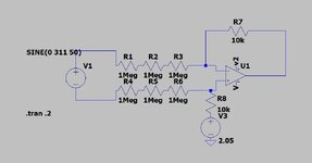
I want to know the dc value calculation of the following graph ,. i used an approximately 1.75 dc offset volt the for the given sinewave ,Then what will be the total dc rms value ,How to measure it ?

11.jpg
 

Hi,

RMS signals ar added using squares.

U_RMS_total = sqrt( U_RMS_1 ^2 + U_RMS_2 ^2 + U_RMS_3 ^2 +...)

U_DC = U_RMS

Klaus
--- Updated ---

Then what will be the total dc rms value
...not "DC"

And your picture shows a DC shift of about 2.05V .. not 1.75V

Klaus
 
Hi,

RMS signals ar added using squares.

U_RMS_total = sqrt( U_RMS_1 ^2 + U_RMS_2 ^2 + U_RMS_3 ^2 +...)

U_DC = U_RMS

Klaus
--- Updated ---


...not "DC"

And your picture shows a DC shift of about 2.05V .. not 1.75V

Klaus
Thanks sir ,
sorry
May i know the RMS value of the above example ,I dint corectly get how the rms calculated ?
--- Updated ---

Sir Please watch the video here the amplitude of the sinewave is variying frommaximum to low, but the volt reading in multimeter is always same .why the varying dc volt is not showing is it taking the avarage value ?
I want to measure the varying sinewave amplitude is it okayto read an ADC ?

will read the ADC that changes ?
 
Last edited:

May i know the RMS value of the above example ,I dint corectly get how the rms calculated ?
--> Just do an internet serach. It has been answered in text, in video, with math, with example many times all over the internet.

Sir Please watch the video here the amplitude of the sinewave is variying frommaximum to low, but the volt reading in multimeter is always same
If the voltage reading of the voltmeter does not change, then it does not show the RMS value but the (average) DC value. (Most probably. I don´t know how it is connected, nor do I know it´s specifications)

BTW: you say "the varying DC voltage" .. but the "DC voltage" does not change. It´t the RMS voltage that changes.

I want to measure the varying sinewave amplitude is it okayto read an ADC ?
The ADC reads instantaneous values.
Now you talk about the "amplitude" ... a new measure of voltage.

I´m confused now what you really need to know.
--> define what you need to know.

****
And if you want us to find/recommend a solution you need to define the input signal.
* Does the DC vary? --> tell us min, value, max value, and how fast it may change.

* The "AC": is it pure undistorted sine? No overtones, low noise? What´s the amplitude min, max? What´s the frequency min, max?

Klaus

Sir
I require to read by using an ADC that the value which have a combination of a sinusoidal AC waveform with an amplitude of sinewave volts and a DC offset volts .

( an example follows for better understanding
A sine wave with a peak-to-peak voltage of 4 volts and it has been shifted by an offset voltage of 5 volts,
So the output is output is a combination of DC and AC components.)


I am here actually doing that measuring an ac having 230volt 50hz which hasbeen droped out by highvalue resistance and given to a opamp in diffrential mode ( flaoting mode) , the opamp gives a very low gain , A Dc offset volt is applied to in noninverting terminal of the op amp .

But when i measur it in multimeter it shows only the offset DC Volt not adding the sinewave , is it averge to zero ?

i am posting a circuit to undersatnd
 

Attachments

  • 1111.jpg
    1111.jpg
    44.6 KB · Views: 66

Hi,
I require to read by using an ADC that the value which have a combination of a sinusoidal AC waveform with an amplitude of sinewave volts and a DC offset volts .
Don´t know what this means.

( an example follows for better understanding
A sine wave with a peak-to-peak voltage of 4 volts and it has been shifted by an offset voltage of 5 volts,
So the output is output is a combination of DC and AC components.)
so this describes the input only. But what output do you expect?

I am here actually doing that measuring an ac having 230volt 50hz which hasbeen droped out by highvalue resistance and given to a opamp in diffrential mode ( flaoting mode) , the opamp gives a very low gain , A Dc offset volt is applied to in noninverting terminal of the op amp .
This often is used to measure mains voltage.

But when i measur it in multimeter it shows only the offset DC Volt not adding the sinewave , is it averge to zero ?
Already answered. Nothing changed since then.

i am posting a circuit to undersatnd
Yes, this is the analog part of what you described above.

*******
The goal is still unclear:

What´s absolutely confusing. you mix every way to measure AC.
You speak about
1) peak-to-peak voltage
2) RMS voltage with DC added
3) RMS voltage without DC
4) amplitude of a sine (without DC)
To me it´s not clear whether you want 1,2,3, or 4.

Your example: (peak-to-peak voltage of 4 volts and it has been shifted by an offset voltage of 5 volts)
gives the following results:
1) 4Vpp
2) sqrt(2 + 25) = sqrt(27) = 5.2V
3) sqrt(2) = 1.4V
4) 2V
Four different values. Which one do you want?

*****
My guess:
You talk about AC measurement. Thus I guess you want to get the RMS value of the mains (sine) input.
If so, you don´t want to add DC (you said so) --> but you want to get rid of DC.

to get this:
ADC_Values (LSB) --> high pass filter (LSB) --> RMS calculation (LSB) --> multiply (Volts)

The high pass filter needs to pass the 50Hz with low gain error. And it neds a fast settling time when supressing DC. You need to find the compromise.
--> you need to tell how much gain error you allow at 50Hz.
--> you need to tell how fast it should get rid of DC. Let´s say less than 1% or so . You tell

--> you need to answer my questions of bottom of post#4.

--> what is your ADC sampling rate?
--> how often (per second) do you need an RMS value output?

If you want me to continue .. you need to provide these important informations as good as you can as values with units.

Klaus
 

with 0Vdc and 10Vp or 20Vpp the Vrms=7.07
with 10Vdc offset Vac is from 0 to 20 Vpp but Vrms = 12.25 Vrms rising by 5.18 due to rms calcularions.
--- Updated ---

Falstad shows realtime Vavg , max, min, avg and rms easier than LTspice

1702497117765.png


Last edited:
In the video you posted I can see an amplitde modulate sinewave with a superimposed DC (from the oscilloscope measurement). The DMM is set on "DC" so it only measures the DC components of the signal that is constant. You coud set the DMM on "AC" to see the RMS (if it is a true RMS voltmeter) but since the measurment is not istantaneuos, but filtered you will not see the actual value but an integrated value over a certain amount of time. Even if the measure will be istantaneous you will not be able to read it since it varies too fast.
You can perform the measurement with the oscilloscope at a given instant placing a couple of cursor to measure the Vpp (peak-to-peak voltage) at the wanted instant. So you can calculate the RMS value of the sinusoid alone as VrmsSin=Vpp/[2*sqrt(2)] then we know that for a DC of value A, also its RMS will be A.
Then applying the rule Vtotrms=sqrt(rms1^2+rms2^2+...rmsn^2) we will have

Vtotrms = sqrt(VrmsSin^2+A^2) that is, taking the values from you post #1:

VrmsSin = (2.4-1.7)/[2*sqrt(2)] = 0.247V RMS value of the sinewave alone
A = 2.05V

that is:

Vtotrms = sqrt(0.247^2+2.05^2) = 2.06V
 
You cannot compute RMS from output with DC unless DC is subtracted, to estimate input Vac rms.

It does not scale properly with your design ratio being 1/300

You can however , capture the average of peak voltages or Vpp and convert to RMS use a FW rectifier with filtering.

Also the resistors might be rated for <= 250V so use 3 on H side and same on low side just for CMRR transient suppression, although adding OV suppression is a good idea.

Are you planning to record transients or brownouts? Then rectify and filter accordingly with multiple analogs.
1702521068597.png
 
Last edited:
Below it LTspice simulation of your (approximate) waveform:
As you can see the calculated RMS value (which includes the DC offset) is slightly larger than the Average value due the RMS value of the sinewave.
A true RMs voltmeter that includes the DC level in its measurement should give the same RMS value.

1702524651691.png
 
Mr Crutchow implies you want average or RMS of the grid voltage. His example had both DC and AC about the same but this is misleading. (see my link for interactive slider and results.)

To measure AC RMS calculations, the DC adds error to the RMS result as the DC level gets higher.

Therefore if you want to measure the AC RMS, it is best that you subtract the DC value from the reading or use a full wave rectifier with a R2R Op Amp, and state your accuracy specs. You can oversample and compute RMS, capture pk and convert or filter FW rectifier and LP filter get average or compute same in S/W.


Bottom Line. Define design specs for accuracy and impulse conditions and input Vac range. Your design can work with 3.3V no problem, but overstress on components, must also be considered with CM lightning noise.
Below it LTspice simulation of your (approximate) waveform:
As you can see the calculated RMS value (which includes the DC offset) is slightly larger than the Average value due the RMS value of the sinewave.
A true RMs voltmeter that includes the DC level in its measurement should give the same RMS value.
 
Last edited:

Thanks experts for the reply,
The avarage of varying dc ( ie sinewave ), ie positive and negative half cycle may be canceled out ?
so the output is getting as the offset DC only ?

output = vmsin(theta) + offset Dc
ie vmsinetheta will be zero ? (its avrage )
is that reason we get only the DC offset volt at the multimeter ?

if i measure the measure the multimeter in AC MODE I get the AC voltage

My thinking is that

I want to measure the shifted vayring voltage (that is the sinewave ) which above the zero level by an ADC .

respected helpers I will back after the adc reading expirements

Thankyou for the valuable comments
 

For me, the question seems misdirected from the start. If a measurement circuit introduces an intentional DC offset like post #5 circuit does, you'll preferably substract the known offset after ADC conversion, as already suggested. As the ADC has a ( hopefully) stable reference voltage, input offset can be derived from the same reference and doesn't need adjustment.
 
If you knew exact frequency and measured average over exactly 1 cycle, the result is DC but measuring it is the obvious way.
The easy method is filter out noise,
1. measure peak-to-peak and convert to RMS by division of 2root(2) or mult. * 0.35356 or
2. FW Rectify then average over N cycles and convert to rms by multiplying * pi/2rt(2)=1.11

If you do not know the exact frequency, 1 is better, and you can certainly take an average of Vpp.
 
you'll preferably substract the known offset after ADC conversion, as already suggested. As the ADC has a ( hopefully) stable reference voltage,

Sir I plan to remove the offset DC by using an voltage divder ? But I think it cannot remove fully the offset dc ? Need to substract some of in software .

Is there any other way to substract that dc ?
 

I understand that the offset is intentionally added in the differential amplifier to shift the bipolar input voltage to unipolar ADC range. That's a standard problem of ADC signal condition and is done so or similarly in many measurement front ends.
Is there any other way to substract that dc ?
Substracting DC digitally is the natural way to do it. Why don't you want it?
 
Sir I plan to remove the offset DC by using an voltage divder ?
This makes no sense at all.

You need to add DC offset for the ADC to work properly (as FvM mentioned)
First you add it on the analog side ... but then you want to remove it on the analog side. ... What do you think you gained by this?

--> You need to subtract the offset on the digital side. That´s the only meaningful way.

I recommend you to read about mains voltage measurement .. or more focussed: measurement of AC voltage using unipolar ADC (input)
There are tons of informations around this topic in the internet. Use this source of information. No need to re invent the wheel.
 
I understand that the offset is intentionally added in the differential amplifier to shift the bipolar input voltage to unipolar ADC range. That's a standard problem of ADC signal condition and is done so or similarly in many measurement front ends.

Substracting DC digitally is the natural way to do it. Why don't you want it?
Sir ,
I asked so ,The DC offset reduce ADC reresolution

forunderstanding my problem i am giving an example

my adc resoultion is 4096
my offset dc volt (resistor bias dividing ) is 1.25 volt
my microcontroller maximum input volt is 3.3volt
Then
Volt_per_bits 3.3/4096 = 0.0008056640625 = 805 micro volt
for DC offset is 1.25 its corressponding adc value is (approximately )1,551.51
then
1,551.51 * 0.0008056640625 = 1.249 volt

So we need to substract1551.51 from the read adc_value to get correct value
4096 - 1551.51 =2,544.49

The final resoultion is 2,544.49

is it corect ( i think so if wrong sorry please correct me )

we get ADC resution is 2544 only :cry:

@FvM and KlausST
sir thats why I asked anyother ways for reading it ?
 

Ideally, 0 V input is mapped to center of ADC range (Offset 1.65 V), +/-AC voltage mapped to full ADC range 0...3.3V. How do you loose resolution?
 
You take ADC readings over the whole waveform.
You then take the average value of all those readings and subtract it from each reading to remove the DC level.
What's left is the AC values from which you can compute the RMS values.
 
Status
Not open for further replies.

Part and Inventory Search

Welcome to EDABoard.com

Sponsor

Back
Top