Shamooooot
Newbie level 6
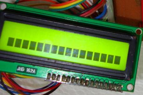
My program doesn't showing anything on the LCD just this row of flags even though the Proteus shows the required results ?

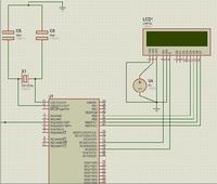
This is the circuit :

and here is my code:
int i;
int n;
char txt[6];
unsigned short adc_val ;
sbit LCD_RS at Rc3_bit;
sbit LCD_EN at Rc5_bit;
sbit LCD_d0 at Rb0_bit;
sbit LCD_d1 at Rb1_bit;
sbit LCD_d2 at Rb2_bit;
sbit LCD_d3 at Rb3_bit;
sbit LCD_d4 at Rb4_bit;
sbit LCD_d5 at Rb5_bit;
sbit LCD_d6 at Rb6_bit;
sbit LCD_d7 at Rb7_bit;
//Pin direction
sbit LCD_RS_Direction at TRISc3_bit;
sbit LCD_EN_Direction at TRISc5_bit;
sbit LCD_d0_Direction at TRISB0_bit;
sbit LCD_d1_Direction at TRISB1_bit;
sbit LCD_d2_Direction at TRISB2_bit;
sbit LCD_d3_Direction at TRISB3_bit;
sbit LCD_d4_Direction at TRISB4_bit;
sbit LCD_d5_Direction at TRISB5_bit;
sbit LCD_d6_Direction at TRISB6_bit;
sbit LCD_d7_Direction at TRISB7_bit;
void main()
{
int R;
LCD_Init();
LCD_out(1,4,"What's");
delay_ms(1000);
LCD_out(1,3,"Up");
LCD_out(2,3,"Edaboard");
delay_ms(1000);
Lcd_Cmd(_LCD_CLEAR);
delay_ms(1000);
LCD_out(1,4,"Done By");
LCD_out(2,3,"Shamooooot");
delay_ms(1000);
Lcd_Cmd(_LCD_CLEAR);
LCD_out(1,4,"thank");
LCD_out(2,3,"you");
delay_ms(1000);
Lcd_Cmd(_LCD_CLEAR);
LCD_out(1,1,"for");
LCD_out(2,1,"helping");
delay_ms(1000);
Lcd_Cmd(_LCD_CLEAR);
adc_val = adc_read(2);
while (adc_val>115)
{
LCD_out(1,3,"WARNING!!!");
LCD_out(2,1,"help needed");
}
}
Thanks all

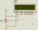
This is the circuit :

and here is my code:
int i;
int n;
char txt[6];
unsigned short adc_val ;
sbit LCD_RS at Rc3_bit;
sbit LCD_EN at Rc5_bit;
sbit LCD_d0 at Rb0_bit;
sbit LCD_d1 at Rb1_bit;
sbit LCD_d2 at Rb2_bit;
sbit LCD_d3 at Rb3_bit;
sbit LCD_d4 at Rb4_bit;
sbit LCD_d5 at Rb5_bit;
sbit LCD_d6 at Rb6_bit;
sbit LCD_d7 at Rb7_bit;
//Pin direction
sbit LCD_RS_Direction at TRISc3_bit;
sbit LCD_EN_Direction at TRISc5_bit;
sbit LCD_d0_Direction at TRISB0_bit;
sbit LCD_d1_Direction at TRISB1_bit;
sbit LCD_d2_Direction at TRISB2_bit;
sbit LCD_d3_Direction at TRISB3_bit;
sbit LCD_d4_Direction at TRISB4_bit;
sbit LCD_d5_Direction at TRISB5_bit;
sbit LCD_d6_Direction at TRISB6_bit;
sbit LCD_d7_Direction at TRISB7_bit;
void main()
{
int R;
LCD_Init();
LCD_out(1,4,"What's");
delay_ms(1000);
LCD_out(1,3,"Up");
LCD_out(2,3,"Edaboard");
delay_ms(1000);
Lcd_Cmd(_LCD_CLEAR);
delay_ms(1000);
LCD_out(1,4,"Done By");
LCD_out(2,3,"Shamooooot");
delay_ms(1000);
Lcd_Cmd(_LCD_CLEAR);
LCD_out(1,4,"thank");
LCD_out(2,3,"you");
delay_ms(1000);
Lcd_Cmd(_LCD_CLEAR);
LCD_out(1,1,"for");
LCD_out(2,1,"helping");
delay_ms(1000);
Lcd_Cmd(_LCD_CLEAR);
adc_val = adc_read(2);
while (adc_val>115)
{
LCD_out(1,3,"WARNING!!!");
LCD_out(2,1,"help needed");
}
}
Thanks all
