Continue to Site

Welcome to EDAboard.com

Welcome to our site! EDAboard.com is an international Electronics Discussion Forum focused on EDA software, circuits, schematics, books, theory, papers, asic, pld, 8051, DSP, Network, RF, Analog Design, PCB, Service Manuals... and a whole lot more! To participate you need to register. Registration is free. Click here to register now.

Why i got the test different S11 with different ground?

Status
Not open for further replies.

John_li

Full Member level 5
Joined
Aug 6, 2005
Messages
272
Helped
9
Reputation
18
Reaction score
1
Trophy points
1,298
Activity points
2,945
Hi all,
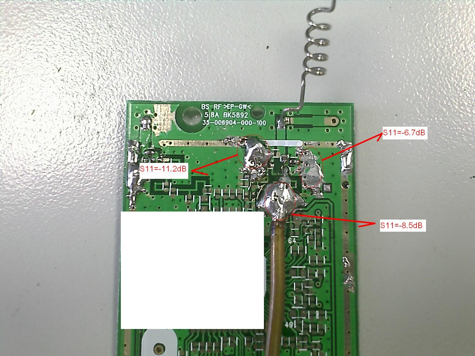
I measured 5.8G helix antenna(S11 parameter) soldered with different gounds as photoes.And I got the different results,i do not know what cause the different results,anyone can help me?


Thank you
 

At 5.8 GHz, your feeding cable to PCB interface can be expected to have already a considerable reflection coefficient. It can't be identical for the three cases.

The cable position also affects the antenna impedance to some extent.

Generally, the effects could be better understood from a S11 frequency sweep, it would reveal e. g. resonances.
 

    John_li

    Points: 2
    Helpful Answer Positive Rating
Thank you for reply.And any criteria to obey?and how to select the correct point ?Any theoretics to explain the differnce?
 

Status
Not open for further replies.

Part and Inventory Search

Welcome to EDABoard.com

Sponsor

Back
Top