- Joined
- Jan 22, 2008
- Messages
- 52,476
- Helped
- 14,756
- Reputation
- 29,794
- Reaction score
- 14,119
- Trophy points
- 1,393
- Location
- Bochum, Germany
- Activity points
- 298,329
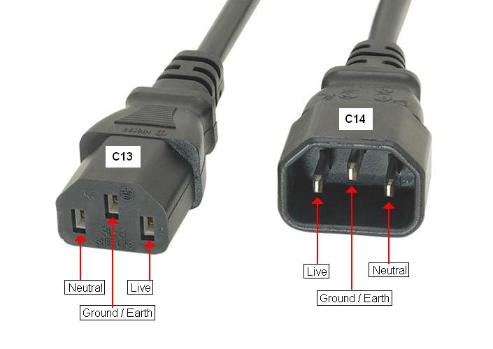
Re: Which from the "1" and "2" black wires are the neutral and live?
https://en.wikipedia.org/wiki/AC_power_plugs_and_sockets
https://en.wikipedia.org/wiki/Mains_power_around_the_worldHow do I find out if the mains connector is unpolarized?
https://en.wikipedia.org/wiki/AC_power_plugs_and_sockets
")