Continue to Site

Welcome to EDAboard.com

Welcome to our site! EDAboard.com is an international Electronics Discussion Forum focused on EDA software, circuits, schematics, books, theory, papers, asic, pld, 8051, DSP, Network, RF, Analog Design, PCB, Service Manuals... and a whole lot more! To participate you need to register. Registration is free. Click here to register now.

What's the best way to get 3.3V from a 5V circuitry?

Status
Not open for further replies.

min2max

Advanced Member level 4
Joined
Jul 12, 2011
Messages
104
Helped
7
Reputation
14
Reaction score
7
Trophy points
1,308
Location
China
Activity points
2,209
I want to use a SHT11 sensor to measure relative humidity. As said in the datasheet, although it's ok to use a 5V power, 3.3V is recommended.

I want to know what's the best way to get 3.3V voltage in a 5V circuitry with a PIC18F4550 MCU.

Can I use the DAC module to get a quite precise 3.3V output to drive this sensor?

Thanks in advance.
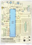
 

I have scanned page 33 of the March 2011 issue of the Australian electronics magazine - Silicon Chip.

The top of the diagram shows how they derived the 3.3 Volt in their Maximite Computer design.

In the accompaning text, they say that you can calibrate the voltage reading by measuring the 3.3 Volt line with a DMM & then include that value in the PIC programme to calibrate the measurements.
 

Attachments

  • Maximite.jpg
    Maximite.jpg
    344 KB · Views: 185
Thank you so much, ljcox.

Your solution is to use a voltage regulator (3.3V) which is similar to 7805 (5V). This seems to be a 'standard solution', right?
 

I'm also interested in other solutions, especially with less components.

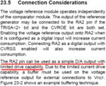
Here is an excerpt from the dadasheet of PIC18F4550.

Snap1.png

Is it possible to use PIC itself as a programmable (low consumption) power source? I'm not familiar with this and look forward to any information/help.
 

Hello!

Can I use the DAC module to get a quite precise 3.3V output to drive this sensor?

Generally speaking, this is a very bad idea. Of course, if the consumption of the
device you want to power is in the µA / mA range, this may work.
If the maker specifies clearly that it can be done, then do it. Otherwise, use a regulator.
But the purpose of a DAC is not to supply power, but to supply a voltage corresponding
to a numerical input and nothing more.

Now for your question, you have already some replies. If you want a low footprint
design, you can use for instance Microchip's MCP1700-33. Or another similar device
from TI: TPS73233 which has also an enable pin, allowing you to shutdown the 3.3V
output.

Dora.
 
  • Like
Reactions: min2max

    min2max

    Points: 2
    Helpful Answer Positive Rating
Thank you for your information, doraemon.

It's yet another demonstration of for any single specific design demand there're always a bunch of solutions to select from.

I was also guessing the method using DAC as power source is at least not a good idea.
 

The list would not be complete without these simple ways to get 3.3V from 5V.

* Zener diode method (in parallel with load). 3.3V is a standard value in the 500mW variety. Or make a stack of 5 diodes, or 2 led's, etc.... if they can be chosen to have the necessary fwd V threshold. Using led's is suitable only for very light loads.

* Voltage drop method (in series with load). You can get 1.7V drop using 1 led, or a string of 3 diodes. Even though the usual figure we hear is 0.6V per each, this figure decreases slightly with lower current draw. Then the drop might only add up to 1.7V total. The diodes have to be chosen for the necessary fwd V threshold.

* Simple voltage regulator based on 1 transistor. Useful for higher current draw. The zener will need to be 3.9V, a standard value in the 500mW line. A substitute could be 2 led's and 1 diode.


Linear regulator - Wikipedia, the free encyclopedia
 
  • Like
Reactions: min2max

    min2max

    Points: 2
    Helpful Answer Positive Rating
Thank you Brad. They are inspiring.

This is the way I like very much - to make a list of alternatives as complete as possible even though some of them are not needed and/or not very suitable at the very time the demand initially arose.

I once also thought of the approach of voltage divider and zener clamping.

I hope this thread could continue evolving and eventually becomes a complete list of tips on VOLTAGE REGULATION.
 
Last edited:

Hi,

The SHT sensors do run at 5v ok, many ciruits around doing just that.

However, if you do drop the voltage to 3v3 for just the sensor then you will need a bi-directional voltage translator to connect the 3v3 Sensor with the 5v Pic.

**broken link removed**
 

hi wp100,

Thanks for the information.

It's my first time of using humidity sensor of SHT series. Its accuracy (+/-3%) is not very high (in my opinion) but is still not significantly lower than SHT15/75, which are incredibly expensive. After reading the datasheet, I got an impression that it is very fragile - quite sensitive to its working/storage environment, including temperature, some special substances, gases, etc. and that if I'm not very careful, that nominated accuracy can even not be be guaranteed.

The datasheet says - "The supply voltage of SHT1x must be in the range of 2.4 – 5.5V, recommended supply voltage is 3.3V."

It's the above impression that makes me tend to stick to the "recommended" voltage. Honestly speaking, it's a sign of lack of confidence of the performance of the device.

wp100, do you have any experience comparing its accuracy under 5V supply and 3.3V recommended voltage?
 

I've used zeners to interface 3.3 volt bluetooth modules to a 5 volt system, and found the result very satisfactory.

There are many java applets to help you calculate the series resistances. One such: Zener Diode Calculator

Regards,

Anand Dhuru
 

hi wp100,

Thanks for the information.

It's my first time of using humidity sensor of SHT series. Its accuracy (+/-3%) is not very high (in my opinion) but is still not significantly lower than SHT15/75, which are incredibly expensive. After reading the datasheet, I got an impression that it is very fragile - quite sensitive to its working/storage environment, including temperature, some special substances, gases, etc. and that if I'm not very careful, that nominated accuracy can even not be be guaranteed.

The datasheet says - "The supply voltage of SHT1x must be in the range of 2.4 – 5.5V, recommended supply voltage is 3.3V."

It's the above impression that makes me tend to stick to the "recommended" voltage. Honestly speaking, it's a sign of lack of confidence of the performance of the device.

wp100, do you have any experience comparing its accuracy under 5V supply and 3.3V recommended voltage?


Hi,

I've only run them under 5v, cannot see this changing the accuracy of the device in any way, nothing in the datasheet implies it would do so.

The 3% accuracy is only over the range 20 to 80 %, much less so outside these figures.
However the SHT range are some of the more accurate devices but at a price as you have found out.

Think many humidity sensors are designed for air conditioning units / humidifiers etc where accuracy is not so important.
Expect there are some lab grade sensors but its the old story, you gets what you pay for.

Are you aware that there is an updated range of SMD SHT21 and 25s, which have a standard I2C interface instead of the custom ones used by the SHT11s.

For the SHT11 range there is also a protective cover available, though cannot just find the part number to hand.

I ran one ok for a while but then made an error in re-connecting it to an unpolarised plug and promptly blew it.

Because of the expense I looked for something cheaper that was a similaly intergated temp and hum rather than making one from parts.

Ended up using the DHT11 sensors which seem to come out of China, while giving good sounding figures in the datasheet the practical accuracy was poor, but the humidity was good enough for my purposes.
**broken link removed**
The newer DHT22 is supposed to be more accurate, if you can find a stockist.

I was just about to order one of these now the supplier has them back in stock at a fair price
**broken link removed**

Are you aware of the salt box method of checking their accuracy at 75%.
 
  • Like
Reactions: min2max

    min2max

    Points: 2
    Helpful Answer Positive Rating
...

The datasheet says - "The supply voltage of SHT1x must be in the range of 2.4 – 5.5V, recommended supply voltage is 3.3V."

It's the above impression that makes me tend to stick to the "recommended" voltage.
The SHT sensors do run at 5v ok, many ciruits around doing just that.
I've only run them under 5v, cannot see this changing the accuracy of the device in any way, nothing in the datasheet implies it would do so.

Obviously, some concrete comparison would be helpful. When time permits, I'll have some tests and report here.

---------- Post added at 02:08 ---------- Previous post was at 01:58 ----------

Thanks for the information, ard.

Yes, zeners are our good friends here. And, indeed, among the methods mentioned by Brad, the simplest solution of my need is just a LED (in series with the SHT chip). The only downside one might think as is that he or she might feel the light emitted by the LED annoying if it's not needed (I don't know how intense it would be though - I guess it would be very dim because SHT features quite low power consumption)

---------- Post added at 02:46 ---------- Previous post was at 02:08 ----------

The 3% accuracy is only over the range 20 to 80 %, much less so outside these figures.
However the SHT range are some of the more accurate devices but at a price as you have found out.
I'm awear of that. Thanks.

Think many humidity sensors are designed for air conditioning units / humidifiers etc where accuracy is not so important.
Yes, that accuracy is perhaps higher than enough for that specific applications.

Are you aware that there is an updated range of SMD SHT21 and 25s, which have a standard I2C interface instead of the custom ones used by the SHT11s.
I've not noticed that difference. Currenty, what I care more is its accuracy instead of interface convention - as long as they are not too difficult to implement in practical aspect.

Because of the expense I looked for something cheaper that was a similaly intergated temp and hum rather than making one from parts.

Ended up using the DHT11 sensors which seem to come out of China, while giving good sounding figures in the datasheet the practical accuracy was poor, but the humidity was good enough for my purposes.
**broken link removed**
The newer DHT22 is supposed to be more accurate, if you can find a stockist.

I was just about to order one of these now the supplier has them back in stock at a fair price
**broken link removed**

Are you aware of the salt box method of checking their accuracy at 75%.
Yes, the prices of SHT series are worth a serious consideration at a customer's standpoint. I have also found some alternatives, some as you've mentioned. But just again as you've also mentioned, some products have a relative higher nominated performance than in practice (that's a shame), and unlike other physical quantities, e.g, temprature, I cannot readily found a reference to check its accuracy. That's why I turned to SHT series on which I seem to have more faith. (In general, I judge a product, say a component, heavily by its datasheet. This sounds like a little bit contradiction to what I've said above - what I meant is that I judge them not by what they are advocating, but by the feeling I got from the material.)

Thanks for your information.

I have no idea of the application of salt box method in humidity measurement. Could you please elaborate?
 
Last edited:

Using 3 silicon diodes of typical 0.6V drop each :

+5.1V--------------|>|---------------|>|------------------|>|------------------+3.3V
 

Hi Externet,

This is one of the methods mentioned by Brad - probably the second cheapest solution.

Thanks.
 

How about using 3.3v for whole circuit?

-ichan
 

Yes, that's indeed another exceptionally simple solution - because PIC18F4550 also works with 3.3V (but I'm not sure if other devices in my cirtuit do so). The reason I'm using 5V is I can get this voltage easily from a USB port or any existing adapter, say those for an iPad or a Kindle.

Now that 3.3V and 5V are all frequently used in various kind of device, it'll be helpful to make another list of frequently used power voltages and their pros and cons.

I hope this is not so off-topic from the moderator's point of view.
 
Last edited:

Here is another excerpt of the PIC18F4550 datasheet:

3V3_regulator.png

Is there a way to make use of this built-in 3.3V regulator?
 

Hi,

I have no idea of the application of salt box method in humidity measurement. Could you please elaborate?

Just do a web search , there are plenty of details, its a simple way to check the calibration of a humidity sensor at 75%.

The biggest problem with temp and hum sensors is finding a source to check their accuracy against, sounds easy but just try and find something - unless you have access to reference devices at work or uni.


The reason I'm using 5V is I can get this voltage easily from a USB port or any existing adapter, say those for an iPad or a Kindle.

If you are looking to get accurate, stable results, then a USB ports power source is not the best way.

From practical experience I know even a desktops USB can cause strange problems with your circuitry.
Laptops USB ports are well known to cause problems with USB programmers.

The output voltage is always going to be on the low side of 5v so prehaps running your whole circuit at 3v3 through a well regulated and very well filtered power supply might be the better way.
 

Just do a web search , there are plenty of details, its a simple way to check the calibration of a humidity sensor at 75%.

The biggest problem with temp and hum sensors is finding a source to check their accuracy against, sounds easy but just try and find something - unless you have access to reference devices at work or uni.

Aha, through web search with your hints I am now able to check the calibration of my sensor (at 75%). Thank you very much!

How to Measure Humidity in a Room | eHow.com

Currently, I don't need to check it at other RH levels other than 75% - what I want is an idea of how accurate the sensor is comparing to what is advertised.

If you are looking to get accurate, stable results, then a USB ports power source is not the best way.

From practical experience I know even a desktops USB can cause strange problems with your circuitry.
Laptops USB ports are well known to cause problems with USB programmers.

The output voltage is always going to be on the low side of 5v so prehaps running your whole circuit at 3v3 through a well regulated and very well filtered power supply might be the better way.

Glad to know that. Sometime I may give it a test/try.

And I'd like to hear your opinion on how to determine/select the work voltage of any task.
 
Last edited:

Status
Not open for further replies.

Part and Inventory Search

Welcome to EDABoard.com

Sponsor

Back
Top