Continue to Site

Welcome to EDAboard.com

Welcome to our site! EDAboard.com is an international Electronics Discussion Forum focused on EDA software, circuits, schematics, books, theory, papers, asic, pld, 8051, DSP, Network, RF, Analog Design, PCB, Service Manuals... and a whole lot more! To participate you need to register. Registration is free. Click here to register now.

What's the best way to get 3.3V from a 5V circuitry?

Status
Not open for further replies.
Hi,

what I want is an idea of how accurate the sensor is comparing to what is advertised.

The problem is finding a calibrated and certified reference humidity meter to compare the SHT11 against.

I do not know of any readily available but expect they are around in commercial and college use.


And I'd like to hear your opinion on how to determine/select the work voltage of any task.

Depends what your exact task is and the parts used.

With respect to the USB ports power suply, well thats just my limited opinion of using USB ports as a power source.
There are cleary loads of PC equipnemt running fine on usb.

Think there are many more experienced member / engineers in this forum who can give a better more qualified answer your point.
Perhaps start on new post on just that point.

If you are wanting an ideal power source for critical test measurements then use battery power.
 

Using Silicon diode in series is one way second way is you can also you pot configuartion i.e. resistor devide network with capacitor at the voltge feeding terminal....and the most delicated way is use anothere regulator for 3.3 v.....also you can use ziner diode (3.3v) too based on the power rating of the your sensor
 

Thanks milind.a.kulkarni.

The wiki page:

Zener diode - Wikipedia, the free encyclopedia

says: "Breakdown voltage for commonly available zener diodes can vary widely from 1.2 volts to 200 volts."

That's a quite wide voltage range!

What are the 'standard' breakdown (or clamp) voltages that are available in the market?
 

you might consider using this voltage regulator,
RT9163-33

Vin=5.0v(min)
Vout=3.3V

just g00gle it anyway.
 

Hi,

The SHT sensors do run at 5v ok, many ciruits around doing just that.

However, if you do drop the voltage to 3v3 for just the sensor then you will need a bi-directional voltage translator to connect the 3v3 Sensor with the 5v Pic.

**broken link removed**

What is a voltage level translator? Why should I use one if I apply 3.3V just on SHT?
 

Hi Onigece & sreepss,

Thanks for your information.
 

Use LM 1117-3.3V standard regulator.. it was work wll and can provide a current up to 500ma.
 

What is a voltage level translator? Why should I use one if I apply 3.3V just on SHT?

Because the signals from your Pic at 5v and the SHT11 at 3v3 are different.

A High signal from the SHT11 is 3v3 at best, that can be too low to be properly recognised as a High Input to the 5v Pic.

So you need a Voltage Translator / Converter in Both directions as the Pic talks both ways with the SHT11.

https://www.microchip.com/stellent/groups/techpub_sg/documents/devicedoc/en026368.pdf
 
  • Like
Reactions: min2max

    min2max

    Points: 2
    Helpful Answer Positive Rating
Thank you wp100. I once mixed up with voltage regulator and translator.

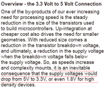
I indeed have this 'tips 'n tricks' at hands but no time to have a good read. The opening of Chap.8 gives a quite good answer to one question I've raised in this thread - It gives a brief explanation of the reason why 3.3V 1.8V etc. have got their place.

Snap4.png
 

Status
Not open for further replies.

Part and Inventory Search

Welcome to EDABoard.com

Sponsor

Back
Top