Continue to Site

Welcome to EDAboard.com

Welcome to our site! EDAboard.com is an international Electronics Discussion Forum focused on EDA software, circuits, schematics, books, theory, papers, asic, pld, 8051, DSP, Network, RF, Analog Design, PCB, Service Manuals... and a whole lot more! To participate you need to register. Registration is free. Click here to register now.

What should be the ADCON1 value?

Status
Not open for further replies.
Joined
Jul 25, 2012
Messages
1,192
Helped
171
Reputation
342
Reaction score
162
Trophy points
1,343
Activity points
0
Hello!

I am running PIC18F46J50 at Fosc = 20MHz. I have configured ADCON0, ANCON0, and ANCON1 registers.
I want to know what should be the value od ADCON1 register.

The bit 7 and 6 will have values 1 and 0, but I want to know what should be the values of bit 5 - bit 0.

That is ACQT2-ACQT0 and ADCS2-ADCS0. It is not mentioned in the datasheet the min TAD required and the time for 1 TAD.

The datasheet is here http://ww1.microchip.com/downloads/en/devicedoc/39931b.pdf

-------Update--------------

I am using thes values are they ok?

ADCON0 = 0b00000000;
ADCON1 = 0b10110101;
ANCON0 = 0b11111100;
ANCON1 = 0b00011111;

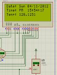
I get 150 degrees C for 150 degrees C but when i go on decreasing the value of temperature, I get a variation of 5 degree C.

I am attaching an image, the values are different.


Regards
Jayanth D
 

Attachments

  • error.jpg
    error.jpg
    124.7 KB · Views: 89
Last edited:

Check page 523.

1 TAD = 25.0µs (max)
Conversion time = 11 to 12 TAD

Hope this helps.
Tahmid.
 
Last edited:

Hi! Tahmid

Please check the posts at this link. http://www.microchip.com/forums/tm.aspx?tree=true&high=&m=685495&mpage=1#

min TAD is 0.7us and the datasheet says that the TAD should be as less as possible but greater that the minimum TAD. So I chose Fosc = 20 MHZ, Tosc = .05us

min TAD = 0.7us, 16 * Tosc = 0.8us which is greater than the minimum TAD required. So the value of ADCS2-ADCS0 = 010

Should I use 25us for TAD as mentioned in page 523?

If I choose TAD = 25us then

12 TAD = 300us

2 TAD between conversion = 50us

If I Choose TAD = 0.8us then

12 TAD = 9.6us

2 TAD between conversions = 1.6us

Please, Solve my problem.

Regards
Jayanth D
 

FOSC/16 should be okay, since TAD > minimum value of 0.7us. However, it's very close to the minimum (very small margin). So, just use FOSC/32. A slower conversion won't decrease your accuracy. If anything, it will increase accuracy. So, for ADCS<2:0>, use 010 or maybe even 110 (FOSC/64).

Can you upload your project file, hex file and simulation so that I can take a look?
 

Here are the files. How should I connect VDDCORE/VCAP pin?
 

Attachments

  • RTC ADC SD Datalogger v2.rar
    180.2 KB · Views: 92
Last edited:

Well, I can't simulate this. As soon as I run simulation, my computer hangs.

Anyways, in the code, I see that you've used the line:
Code:
ADC_Init();
and then
Code:
ADC_Read();

So, you've used the mikroC library function.
So, you don't need to bother with conversion time and acqusition time. Just set which pins to be analog and which to be digital. Have a look at the mikroC PRO for PIC ADC library: https://www.mikroe.com/download/eng/documents/compilers/mikroc/pro/pic/help/adc_library.htm

mikroC will overwrite your conversion and acquisition time settings anyway.

However, instead of using
Code:
ADC_Read();
use
Code:
ADC_Get_Sample();

Hope this helps.
Tahmid.
 

OK. I used ADC_Get_Sample(0); but getting the same wrong values.

Check with this file. I have included mcHID.dll. put it in windows\system32 folder and then rum the simulation. maybe usb hid is hanging the simulation.

The Schematic is here
 

Attachments

  • RTC ADC SD Datalogger v3.rar
    192.5 KB · Views: 101
  • mcHID.rar
    136.1 KB · Views: 57
  • schematic.gif
    schematic.gif
    436.4 KB · Views: 87
Last edited:

I still can't simulate it. Can you remove the USB parts and upload the files?

By the way, explain this line:
Code:
temp = temp * 0.1488096714381661;

The problem may be here. I think that the constant is inaccurate.

Did you use D1 and D2 to increase the output voltage by 1.4V?
 
Last edited:

Instead of doing something (1.85 * 1024)/1.87

I did like this

I get 1007.999 raw adc value for 150 degree centigrade

LM35 is linear and my adc range is 0-1023

AVdd = 1.87v

Avss = 0v

If 1007.999 * x = 150 then

x = 150 / 1007.999 = 0.1488096714381661

that is used to calculate and conver temp value

temp = temp * 0.1488096714381661


Where is D1 and D2?

I have attached the code with out usb code.

Thanks
Jayanth D
 

Attachments

  • code_tahmid.txt
    9.9 KB · Views: 58
Last edited:

Instead of doing something (1.85 * 1024)/1.87

Where did you get 1.85?

I get 1007.999 raw adc value for 150 degree centigrade
How?

Where is D1 and D2?
Connected in series from LM35 ground to circuit ground. Why did you do this?

I'm sure the error is in the constant.

Remove D1 and D2 and connect LM35 ground to circuit ground.
For 150'C, you'll get 1.5V output. ADC reference = 1.875V
So, that'll give ADC reading of 819.2

So, constant is 150/819.2 = 0.1831054688.....

The way the circuit is arranged, I don't think a linear relationship is maintained.

Hope this helps.
Tahmid.
 

Actually, I want to measure temp from -55 to + 150 degree centigrade. That is why I have used the diodes. I will read adc(0) and adc(1) and take the difference of the 2 values.

OK. I did as you said, but after removing the diodes, the values don't vary in real time.
 
Last edited:

So, you should do that in this code as well. Because of the 2 diodes, you don't have a proportional relationship as in (y=mx), but a linear relationship as in (y=mx+c). That's why for other temperatures the formula you used doesn't work.
 

Please check my previous post. the adc is hanging after i remove the diodes. Even rtc is hanging.
 

RTC doesn't run and adc value doesn't change on changing the LM35 temp value.

I have attached the video. You are right, by removing the diodes i am getting the right values, but how to remove hanging?

- - - Updated - - -

OK. I got it working. The USB HID enable code was commented out. and I was trying to write to usb. OK. The problem got solved. Thanks once agian Tahmid. You found the correct problem. after removing the diodes it is giving the right values.

working project video is attached.

Thanks
Jayanth D
 

Attachments

  • hanging.rar
    249.5 KB · Views: 53
  • working.rar
    448.9 KB · Views: 52

Status
Not open for further replies.

Similar threads

Part and Inventory Search

Welcome to EDABoard.com

Sponsor

Back
Top