rob1310
Newbie level 2
Hello..
I am trying to build an Amp crcuit for an input voltage range between 28mV-59mV from a transducer.
I am using the LM324 amp for this purpose. I built the circuit on a PCB later on to bang into a few problems. SO now i am trying to understand the op-amp and itfunctions.
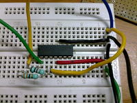
I built a basic amp circuit
Rf = 1000 Ohm;
R1 = 33 Ohm
input is given too 2nd pin of lm324 which has to result in a negative ouput
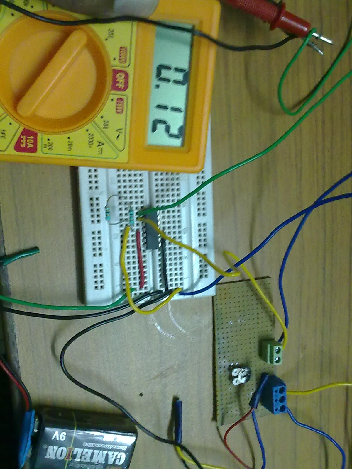
but the output obtained is show in this link below..

the circuit is show as
Can you please send me ur feedback as to what basic connections have to be done on a LM324..
Why am i not getting a negative voltage output which is designed according to the GAIN.. Av = - Rf / R1..
Added after 17 minutes:
Voltage suply for OP-AMP = 9v
Input voltage to pin 0.15V at pin no 2 .. the inverting input pin of LM324//
I am trying to build an Amp crcuit for an input voltage range between 28mV-59mV from a transducer.
I am using the LM324 amp for this purpose. I built the circuit on a PCB later on to bang into a few problems. SO now i am trying to understand the op-amp and itfunctions.
I built a basic amp circuit
Rf = 1000 Ohm;
R1 = 33 Ohm
input is given too 2nd pin of lm324 which has to result in a negative ouput
but the output obtained is show in this link below..
the circuit is show as

Can you please send me ur feedback as to what basic connections have to be done on a LM324..
Why am i not getting a negative voltage output which is designed according to the GAIN.. Av = - Rf / R1..
Added after 17 minutes:
Voltage suply for OP-AMP = 9v
Input voltage to pin 0.15V at pin no 2 .. the inverting input pin of LM324//