aht2000
Junior Member level 3

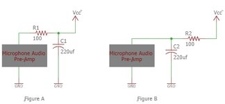
Reference attached drawing, is the following a correct interpretation of the role of R and C in each figure?
Figure A: The RC is to protect the mic preamp from noise coming from the supply or other parts of the circuit.
Figure B: The RC is to protect the rest of the circuit from any noise generated by the mic preamp.
The R and C values are selected based on a rule of thump that the impedance of the C is 10 times less than the R at the subject frequency of interest, and R should be as small as possible to minimize the supply voltage drop based on the preamp expected current consumption?