Continue to Site

Welcome to EDAboard.com

Welcome to our site! EDAboard.com is an international Electronics Discussion Forum focused on EDA software, circuits, schematics, books, theory, papers, asic, pld, 8051, DSP, Network, RF, Analog Design, PCB, Service Manuals... and a whole lot more! To participate you need to register. Registration is free. Click here to register now.

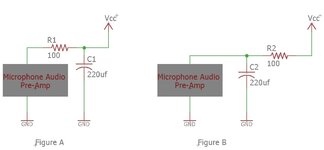
What is the purpose of RC in each of the figures?

Status
Not open for further replies.

aht2000

Junior Member level 3
Joined
Apr 18, 2015
Messages
30
Helped
0
Reputation
0
Reaction score
2
Trophy points
8
Activity points
383
Reference attached drawing, is the following a correct interpretation of the role of R and C in each figure?

Figure A: The RC is to protect the mic preamp from noise coming from the supply or other parts of the circuit.
Figure B: The RC is to protect the rest of the circuit from any noise generated by the mic preamp.

The R and C values are selected based on a rule of thump that the impedance of the C is 10 times less than the R at the subject frequency of interest, and R should be as small as possible to minimize the supply voltage drop based on the preamp expected current consumption?
 

Attachments

  • RC Question.JPG
    RC Question.JPG
    47.7 KB · Views: 111

No. Circuit A has a cap on Vcc perhaps for some reason but the series R has no purpose and active mike uses a pullup R for gain and bias >1k depending on Vcc/Idss x 1/2 for the max swing.

circuit B is a Vcc noise attenuator with T= RC as the breakpoint.

the mic does not have a noise filter shown or likely needed. The BW limiting circuit would be done in the next stage.
 

Hi,

In the picture we neither see the mic nor the signal path, just the power supply to the amplifier.
(Please clarify if I am wrong here)

B) has a resistor from VCC and a capacitor to GND
So this is a low pass filter. If VCC is noisy the circuit will suppress higher frequencies ... to supply the amplifier with more clean DC

A) is not that clear to me.
Usually I'd design a power supply for an amplifier like B).
A series resistor between capacitor and amplifier may cause the amplifier to oscillate in worst case. At least it may cause the amplifier supply voltage to vary with amplifier current, but the supply should be stable.
The circuit makes sense to me, if the amplifier itself has an aditional capacitor at it's supply (we don't see what's inside the box)

Generally I expect that an amplifier causes variable supply current ... and this variable current causes variable voltage at the capacitor. If so, then the voltage ripple at the capacitor is independent of the resistor. (Thus this circuit makes less sense to me)

******
To give more exact answers we need more information about
* wiring (cable? Where in the circuit? What length?)
* whats inside the amplifier box (some HF noise from a switching supply, or an RF receiver/transmitter ...)

Klaus
 

Thank you for the response. I was seeing things differently, but will rethink it again.

When I look at figure A, and imagine high frequency noise super imposed on Vcc from somewhere else, this noise would see a least resistance path through the cap rather than through the 100 ohm, and accordingly this RC setup will filter such noise from reaching the gray box.

While in figure B, I imagine some high frequency signal generated inside the gray box that may leak to the power supply then to other parts of the circuit causing oscillation (may be), so this leaked signal will see a low impedance C2 and go to ground rather than the R2 100 ohm.

The gray box is just a mic preamp as an example, it may be an oscillator, or an amplifier.
 

In general we think of the power source as being the lowest impedance point and as the power is distributed along wiring, the impedance and therefore susceptibility to noise and variation increases. In circuit 'A' the capacitor is just across the supply and may or may not help to keep it stable, as an RC filter 'R' is the supply line impedance so it could be very low, making 'C' relatively ineffective. In circuit 'B', the supply filter really is RC so at the gray box the supply really is filtered.

Note something very important though: The placement of 'C' is critical to operation. Its purpose is to ensure the same signal, whether a wanted one or not, is across its ends. You have to consider what is at the ground of the gray box and what is at the bottom end of the capacitor, to keep the box free of noise ACROSS its supply, the capacitor must be connected across the box. Although topographically correct, if you grounded the capacitor to a noisy point in the circuit, that noise would also appear at the supply to the box, the capacitor would be coupling noise in instead of filtering it out.

Brian.
 

Hi,
When I look at figure A,
Your description exactly fits to figure B. .. but not to figure A.

****

A low pass filter is used to suppress high frequencies.
An RC low pass flter has the "noise" input at the resistor and the output is across the capacitor.
(Please do internet search on RC low pass filter)
This is true for figure A when the noise path is: Vcc --> R2 --> C2 --> GND


***

Your idea about figure B:
It really depends what´s inside the box.
If the noise is a "voltage" noise, then you have an RC low pass filter with the noise path: Amplifier --> R1 --> C1 --> GND

But I rather expect the noise as "current source" (only you know whether this is true or not). And when seen as current source ... R1 is useless for noise filtering. ... but for sure the C still will attenuate high frequency ripple.
Not true in this case: fc = 1 / (2 x Pi x R1 x C1)

Klaus
 

Thank you for the response. I was seeing things differently, but will rethink it again.

When I look at figure A, and imagine high frequency noise super imposed on Vcc from somewhere else, this noise would see a least resistance path through the cap rather than through the 100 ohm, and accordingly this RC setup will filter such noise from reaching the gray box.

While in figure B, I imagine some high frequency signal generated inside the gray box that may leak to the power supply then to other parts of the circuit causing oscillation (may be), so this leaked signal will see a low impedance C2 and go to ground rather than the R2 100 ohm.

The gray box is just a mic preamp as an example, it may be an oscillator, or an amplifier.
A large consideration in this discussion is Capacitor behavior at frequency. Not all
caps at same freq have same ESR, C technology varies significantly. The Polymers for bulk
best overall. "OS-CON" in graph.

1637242103834.png


Regards, Dana.
 

A - use for cable power connect
B - use for LP and slow power ramp up.
220uF is large value compare to <5V application. So its use for filler very low frequency ? :rolleyes:
I think it use for slow ramp up power.
In adudio is any shock power/signal will be "amplifier" and you don't want to hear that.

In my eye, I used both A & B ;) as pi network. It is better to damper noise.
High frequency pass almost through R
Low frequency(DC) pass almost through L (ferrite bead) - Low DCR -> low drop power
Any ringing with different phase between R/L will asorb by R
If using only L (ferrite bead) is not perfect. It really reduce Vpp of high frequency but increase Vpp of base (lower) frequency.
1638004458054.png
 

Status
Not open for further replies.

Part and Inventory Search

Welcome to EDABoard.com

Sponsor

Back
Top