Welcome to our site! EDAboard.com is an international Electronics Discussion Forum focused on EDA software, circuits, schematics, books, theory, papers, asic, pld, 8051, DSP, Network, RF, Analog Design, PCB, Service Manuals... and a whole lot more! To participate you need to register. Registration is free. Click here to register now.
If the ideal (= infinite bandwidth) Opamp exposes output voltage limits, the circuit will also latch to a limit if the input voltage ever touches it.
.
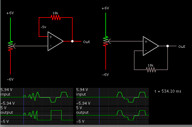
Just to settle the question I've been testing the schematic of post #1 on real hardware.
Feedback at the non-inverting input creates hysteresis, which makes for extremes in response, as well as some uncertainty about the response.
My simulation result (post #2) is incorrect. I should have made the input go above and below the supply rails to the op amp (implied, not shown). This would have brought out the hysteresis.
I re-did the simulation.
Now it behaves correctly but only after the output has gone to either extreme one time. (I wonder if this could be similar to a power-up transient error as mentioned by LvW in post #10?)
The output swings to either extreme suddenly. This occurs at two points where the input is approaching the positive or negative supply rail.
The voltage follower (right) responds the same way as before even with the input going above and below the supply rails.
We think up ideal characteristics for components in the goal of gaining a better grasp on their real (non-ideal) behavior.
My simulation in post #2 failed because the potentiometer did not go all the way to either extreme of supply rail. The simulator apparently let the non-inverting input equal the output, for lack of a normal feedback loop. As others have pointed out, real hardware would not do this.
The algorithm might have used only < or > (greater than or less than). It could have made a difference if it used '<=' or '>='.
Our wise course is to get familiar with how hardware behaves. Simulators can only tell us so much, and if we take our information solely from a simulator then we risk getting fooled (which is what happened to me in post #2).
This link shows a good practice to imitate. The guy sat down with an op amp and charted its output levels as he applied all ranges of levels to the inputs.
J
I re-did the simulation.
Now it behaves correctly but only after the output has gone to either extreme one time. (I wonder if this could be similar to a power-up transient error as mentioned by LvW in post #10?)
Hi BradtheRad, my comments in post#10 applies, of course, to a real macro model only - with internal parts that need power to work and a frequency-dependent gain that causes a feedback delay.
(Otherwise, I don`t know how an ideal opamp model (ideal gain element) could be exposed to power-on transients).
On the other hand - try a simulation based on your model with an additional R-C lowpass (and a buffer, of course). I suppose, the circuit will saturate immediately - even for small input voltages.
Regarding ideal OP parameters, it's the limited bandwidth that makes the positive feedback circuit fail in simulation. It can work well with finite gain and also limited output voltage, as long as the limit is never touched during simulation.
Power-on transients aren't observed in a standard transient simulation, also for a real OP with finite bandwidth, because GBW isn't considered in initial transient solution. If you look at the waveforn of the positive feedback circuit falling into saturation, it starts at t=0 after initial transient solution.
Yes, that`s true. Therefore - when you try to be as realistic as possible you should use a power supply that is switched-on at the beginning of the TRAN simulation.
Such a switch-on is a very good help, for example, to allow self-start of an oscillating device.
Power-on transients aren't observed in a standard transient simulation, also for a real OP with finite bandwidth, because GBW isn't considered in initial transient solution. If you look at the waveforn of the positive feedback circuit falling into saturation, it starts at t=0 after initial transient solution.
The above described effect reminds me on a contribution in an electronic journal with excellent reputation:
A.S. Elwakil: On the necessary and sufficient condition for latch-up in sinusoidal oscillators.(Int. Journal of Electronics, vol.89, No.3, 197-206)
In this article, it is prooved by Elwakil from a system point of view (using the pole distribution in the s-plane) why an IDEAL opamp with dominating positive dc feedback cannot work as an oscillator.
For this purpose, a modification of the classical WIEN bridge oscillator is analyzed that still fulfills Barkhausens oscillation condition - however with net positive dc feedback.
It is shown that (and why) the circuit starts oscillating and exhibits latch-up as soon as the amplitude reaches on of the supply rails.
(Not contained in that paper: It is interesting to note that a REAL opamp model shows another behaviour. It starts NOT oscillating but immediately goes into saturation due to a REAL pole in the RHP of the s-plane)
This site uses cookies to help personalise content, tailor your experience and to keep you logged in if you register.
By continuing to use this site, you are consenting to our use of cookies.