Continue to Site

Welcome to EDAboard.com

Welcome to our site! EDAboard.com is an international Electronics Discussion Forum focused on EDA software, circuits, schematics, books, theory, papers, asic, pld, 8051, DSP, Network, RF, Analog Design, PCB, Service Manuals... and a whole lot more! To participate you need to register. Registration is free. Click here to register now.

What is the output of this Op-amp??

Status
Not open for further replies.
If you derive the equations you will find that it is a working amplifier. But in practice it is highly unstable because of the positive feedback.
That is, in theory if you set a operating point as shown in the pictures from BradtheRad it will give the same output as a voltage follower. If any noise, drift or spike appears at the output it will be feedback to the input then it is going to be amplified at the output (and then again) causing a runnout and the circuit will go to saturation and stay there.
The simulation didn't take that into account.
As long as I know the circuit is useless.
 

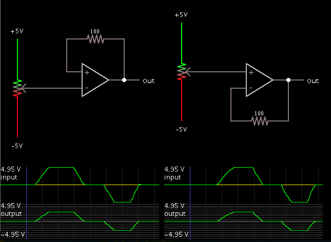
My simulation shows the output follows the input exactly.
Likewise when the inputs are switched around.

The output will smack against one rail or the other and stay there. Any difference between the two inputs is amplified and increases the difference rather than reducing it. As albert says, the circuit is useless.

Keith
 

Yes, Albert`s explanation is correct. The result of BradtheRad`s simulation is wrong because he has assumed (a) an ideal amplifier and (b) that it was powered without any switch-on.
A circuit with positive feedback dc can work only if - at the same time - there is negative dc feedback, which dominates.
 

To the Ineffable All,

That is the reason why Bob Pease was wary of Spice. Ratch

**broken link removed**
 

keith and LvW gave a clearer explanation than mine. I can add that the difference is amplified by the open loop gain of the op amp and that is huge. So a small difference will reach saturation (output to the rail voltage) almost instantaneously.

Articles from the late Bob Pease are very worth to read as they teach a lot. As well as his book that I avidly read and recommend. May be if I read it a 2nd, 3rd ... times I will understand more than a few percent of what I was able to grab the first time. This guy made a lot of contributions and deserves hommage.
 

of course it will work. the point is whether it will do what you think it will do.

so the question is - what do you want it, or think it will do ?

Would Vin be amplified?

and what is the relation between Vin and Vout ??

...
This is a simple problem I solved .. It sums up everything I know about op-amp
https://i.imgur.com/7cUJm.jpg
 

To the Ineffable All,
That is the reason why Bob Pease was wary of Spice. Ratch
**broken link removed**

Hi Ratch, I am not quite sure if - in this case - we should blame the simulator.
In contrary - the simulation program has made no error.
The user (here: BradtheRad) has selected a simplified and idealized amplifier model without any delay and without any power switch-on transients.
As a result, the program has produced an output signal that can be verified also by hand calculation.
However, the simulation was based on totally unrealistic conditions, and the result is completely meaningless as far as practical applications are concerned.
Here is an illustrative mechanical example: Try to balance one small ball on the top of a larger ball. In theory, this can work - however, everybody knows why it doesn`t.
In summary, in most (if not in all) cases it is the user who makes errors (false inputs, false interpretation of the results) - not the program.


If the transistor is ideal then Vin will equal Vout??? ..
 

If the transistor is ideal then Vin will equal Vout??? ..

which transistor are you referring ? or is this a new question?

if you mean opamp, then you have to interchange the + and - inputs in your circuit. then it will work even for non-ideal practical opamp.
 

which transistor are you referring ? or is this a new question?

if you mean opamp, then you have to interchange the + and - inputs in your circuit. then it will work even for non-ideal practical opamp.

Sorry .. Yeah, I mean op-amp ..

Without changing anything using an ideal opamp .. What would be the relation between Vin and Vout? ..
 

Sorry .. Yeah, I mean op-amp ..

Without changing anything using an ideal opamp .. What would be the relation between Vin and Vout? ..

As mentioned already by keith (post#4) there is no relation between both voltages because the opamp works not in its linear amplifying range. The output is clamped to one of the supply rails.
 

Without changing anything using an ideal opamp ..
If you tell me where to buy an ideal Opamp, I'll answer your question :)
Seriously speaking, an ideal OP would involve infinite bandwidth and can't be implemented as a real component. The imagined ideal OP as well as the discussed simulation results are completely fictive. You can't reproduce it in a real circuit.
 

If you tell me where to buy an ideal Opamp, I'll answer your question :).

you can buy an ideal opamp at an ideal electronics store.

this store has all possible components - including those under development and fictitious components, will source a component tailored to your personal specifications immediately, will sell in retail and bulk, are always stocked, price is always zero, full specifications and app notes are included along with eval kits, and they deliver instantly to your door
:grin:

edit: oh yeah, almost forgot. they also provide support for all time to come. techie appears at your door as soon as you have trouble.
 

One problem is that the positive and negative inputs both being at the same voltage as the output satisfies the equations. The problem is it won't stay there for long with positive feedback.

Keith
 

The output voltage is:

Vo = Vi / ( 1- 1/A) where A is the open loop gain of the op amp. so A>>1
you can disregard 1/A then you have.
Vo=Vi
That is a voltage follower. In theory the same as the standard one with negative feedback.
This is what the simulation of BradtheRad shows.
But in practice it will never work for the reasons that have been discussed before.

So what you are saying ..
If the Op-amp is ideal .. ( I+ = I = 0 ) and ( V+ = V- ) .. Then , Vin = Vout in this circuit ..

and if it is not ideal ,, the op-amp will be saturated and the Vout will be equal to the value of the external power supply ..
right?
 

If the ideal (= infinite bandwidth) Opamp exposes output voltage limits, the circuit will also latch to a limit if the input voltage ever touches it.

If the Op-amp is ideal .. ( I+ = I = 0 ) and ( V+ = V- ) .. Then , Vin = Vout in this circuit ..

and if it is not ideal ,, the op-amp will be saturated and the Vout will be equal to the value of the external power supply ..
right?
Yes, but why don't you try in a simulation yourself? We know because we did before.
 

Status
Not open for further replies.

Similar threads

Part and Inventory Search

Welcome to EDABoard.com

Sponsor

Back
Top