Mbox314
Newbie level 5
Hi all!
I have been trying to build an inverter to go from 14.7V to 120VAC @60hz I have also been trying to learn more about power supplies which I'm find very interesting.
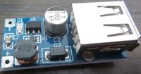
I have been looking around at different designs of power supplies by finding junked ones and taking them apart. While it is not junk I bought a 5V boost converter with a 1-5 volt input and a 5v output for USB gadgets, it cost $2 and I started taking a look at it to see how it works.
I understand the concept of the boost converter and I see most of the parts needed on this board except for some kind of PWM input for the switch. The SOT-23 device has C5 then OC below it. I looked for a datasheet and I think I found it, it says it's a 5.5V voltage regulator.
I don't have a scope with me right now and I wasn't able to trace the leads just yet but how the heck does this thing work? It seems to be missing too many parts? Where is the switching MOSFET (is that the SOT-23 device??) If the SOT-23 is the switching transistor then where is it getting the PWM signal from? shouldn't there be some kind of control IC? Is this a crude unregulated supply that I should toss in the trash?
