Welcome to our site! EDAboard.com is an international Electronics Discussion Forum focused on EDA software, circuits, schematics, books, theory, papers, asic, pld, 8051, DSP, Network, RF, Analog Design, PCB, Service Manuals... and a whole lot more! To participate you need to register. Registration is free. Click here to register now.
I am constructing a push pull amplifier and antenna and was looking for some ideas. Came across a design that has a circuit between the amplifier and inductor bridge.
Would anyone know what its purpose is?
Something doesn't look right, either conceptually dodgy or just poor design.
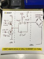
It appears there are two push-pull drivers with the inductor sitting across their outputs, something similar to a H-bridge but with capacitive coupling to the load. The two 100uF capacitors seem to be back to back to make a 50uF non-polarized capacitor with the resistor applying some DC to help keep the polarity across them constant.
I wonder why it is described as an antenna which implies high frequency when such large coupling capacitors are used and transistors that only work at low frequency.
Nothing said about the output waveform and frequency range. An LR bridge is normally operated with sinusoidal waveform and respectively requiring class A or AB driver amplifiers. I see a parallel circuit of electrolytic and ceramic/foil capacitor which probably makes sense for a wider frequency range. Bipolar respectively anti-serial connected electrolytic capacitors can typically work without a dedicated bias circuit.
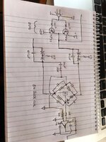
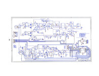
Thanks for all your inputs there. I have attached the source file and another file with, as best I can make out, a diagram of the nearest components.
According to the source file, the circuit was used to locate the proximity of LC tags. It used swept frequency TX and measured the amplitude of the signal to determine the distance of the LC tag to the search coil - one of the coils in the bridge. The sweep was approx 100 to 400 kHz. The proximity of the LC tag drew down on the search coil providing a difference between the input signal and the signal on the search coil.
Unfortunately the source file is not clear so a little hard to determine values and notation.
I have prototyped my circuit up to the push pull amplifier, but am interested to know what part the 2 polarized caps and +12V input play as my prototype has an RF application.
Ok now things make a bit more sense. The inductors in the "inductor bridge" are coils that couple to external objects, acting like a wheatstone bridge.
So I presume the RC circuits are meant to block DC down to very low frequencies. The resistor ensures that the electrolytic capacitors are never reverse biased. But at higher frequencies the ESL of the electrolytic caps probably becomes an issue, which is why the 0.1uF cap is added in parallel.
However this won't make the frequency response perfectly flat, probably still has some big lumps in it... I think a current source drive would be preferable, and wouldn't require the capacitors.
This site uses cookies to help personalise content, tailor your experience and to keep you logged in if you register.
By continuing to use this site, you are consenting to our use of cookies.