RFan
Newbie level 4
I ran into this problem while simulating an RF rectifier.
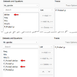
I used harmonic simulation (HB) in the hope of seeing the efficiency of the rectifier. When RLC components are introduced into the circuit, I can see P_Probe1.p and P_Probe1.deltav in the result viewing interface. Otherwise, I can only see P_Probe1.p.
I tried to find the answer in the ADS help documentation and the Internet, but couldn't find it, so I came here to ask for advice.
