Continue to Site

Welcome to EDAboard.com

Welcome to our site! EDAboard.com is an international Electronics Discussion Forum focused on EDA software, circuits, schematics, books, theory, papers, asic, pld, 8051, DSP, Network, RF, Analog Design, PCB, Service Manuals... and a whole lot more! To participate you need to register. Registration is free. Click here to register now.

Voltage measurement technique/circuit in an ac motor drive?

Status
Not open for further replies.

seyyah

Advanced Member level 2
Joined
Oct 7, 2001
Messages
646
Helped
8
Reputation
16
Reaction score
8
Trophy points
1,298
Activity points
6,233
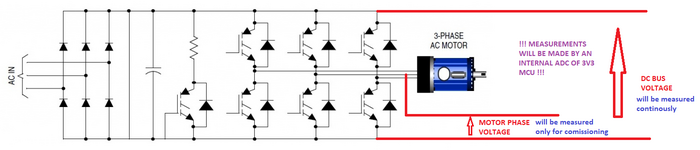
I used to use some kind of voltage sensor to make the isolated measurement of the voltage in a 3 phase inverter system. I've inspected several ac motor drives and I did not see any special IC like isolated amplifier or some sensor or a similar thing. I need to measure the DcBus and motor phase voltage. And they also do. How can they achieve this? Any ideas?
 

Hi,

What's exactly the problem?

DC bus measurement as well as phase voltage measurement is done million times before. I see nothing special.
Do an internet search and you will find hundreds of schematics.

You may do it isolated ... I guess I'd do it non isolated. But I don't know any of your requirements.

Klaus
 

2 or more sets of Divider resistors followed by standard diff amp ( op - amp ) ckt .... it's not rocket surgery ....

For isolation - IL300
 

The problem is cost. If I can eliminate two iso-amps from the circuit, then it will be better from the perspective of total cost. And pcb routing may be relaxed a little, because board area is tight and clearance and creepage rules are hard to follow in a tight area.
 

Hi,

We don't know what you try to do and we don't know how ... unless you tell us.

The most cost effective solution may be "non isolated". I currently don't see the need for isolation.
If "isolated" you could use an SPI ADC and optocouplers on the digital side.
But we don't know resolution, sample rate expected accuracy..

Whether ADC or not,
If ADC, then one included in a microcontroller or an external one...

Please tell us...

Klaus
Think of 3-phase (400VAC phase to phase voltage) fed inverter system. Since Dc Bus is about 550-600VDC, I think isolation is required, am I wrong? There is a flyback transformer in the system with multiple outputs. May be I can manage to sense Dc Bus voltage somehow using one of the outputs. Because there will be a ratio between the outputs and the input(which is connected to the Dc Bus) but motor phase voltage is independent of the bus system so it requires another method. ADC is in the microcontroller normally. ADC resolution 12bit would be better but 10bit would be suffice. ADC conversion speed has no importance. Even 50-100sps would suffice.
 

Since Dc Bus is about 550-600VDC, I think isolation is required, am I wrong?
Not necessarily.
I´m doing 2500V measurement without isolation.

Even 50-100sps would suffice.
I can´t see how this can work. But as long as you give more informations I just have to believe you.
I have have no other chance.

I´m sure I could help you.. but with the given informations I´m unable.
As always with electrical problems: A picture says more than many words. Schematic, photo, wiring scheme, But also clear specifications like motor frequency range, inverter switching frequency....


Klaus
 

Not necessarily.
I´m doing 2500V measurement without isolation.


I can´t see how this can work. But as long as you give more informations I just have to believe you.
I have have no other chance.

I´m sure I could help you.. but with the given informations I´m unable.
As always with electrical problems: A picture says more than many words. Schematic, photo, wiring scheme, But also clear specifications like motor frequency range, inverter switching frequency....


Klaus
Ok. Electrical grid is 50 Hz. Motor frequency range is 0-50Hz. Inverter power will be 7.5KW. Switching frequency will be 4-16KHz. Pretty standart inverter circuit.
 

Attachments

  • inv.png
    inv.png
    123.3 KB · Views: 95

Hi,

No microcontroller, no microcontroller supply?

If you want to discuss about isolation, then usually because two parts are isolated from each other.
Two parts. Where in your picture are the two parts?

********
When the motor frequency is 0..50Hz, and the switching frequency is 4...16kHz, how can Nyquist requirement fulfilled?
What is your idea?

Klaus
 

Added:
Summary. Correct me if I'm wrong.
You want to do measure two values:
1) DC bus voltage. I't's up to 600V DC
So source of information is the DC bus voltage --> something inbetween --> destination is processing in the microcontroller.
What we need is all the information from source to destination.
Source: It surely is with some ripple. The ripple mainly is because of rectified mains frequency, inverter switching frequency and motor frequency, maybe other noise. How to handle the ripple? Do you need to know it? Do you want to get rid of the ripple?
Destination: isn't an amplifier, not the ADC, not the microcontroller pin. It's where the "DC-bus-value" is used in software.
Example: if you want to get rid of the ripple, then this could be done by hardware analog low pass filters, it could be done by the ADC, but it could also be done with a digital filter (software).
Something inbetween: maybe analog filters, maybe analog isolators, maybe ADC, maybe digital isolators, maybe digital filter, maybe something else.

There are many ways to get to the result, thus we need to know your ideas and requirements.

2) motor phase voltage.
Source: your picture shows "phase to negative_DC_bus". Maybe this is what you want.
An ADC gives an instantaneous value. Thus the measurement like shown in the picture will give either
* close to zero (when the lower IGBT is ON)
* close to DC bus voltage (when upper IGBT is ON)
* or something inbetween (when both IGBTs are OFF)
Thus a single ADC value gives no information about motor voltage. Because the motor does not know about negative_DC_bus.
The motor has just the three phases. Thus one often measures the voltage between the (two or three) motor phases.
And without further processing you always get instantaneous values in the range +/-DC_bus_voltage.
Still no useful information.
Thus you need to clearly define what your destination is: Often: RMS value of (fundamental) motor phase-to-phase voltage.
And often you want to get rid of the switching frequency.
What is your idea? Tell us.

If you want to reduce part cost: You should reduce hardware and shift the effort to software.

You need to tell us about the microcontroller. Maybe it is used to control the IGBTs, mabe it's GND is connected to negative_DC_bus, maybe not.
Maybe it's completely isolated, maybe it is not. We don't know as long as you don't tell.

Klaus

Why is the nyquist a problem? Every drive in the market works in similar conditions and their output frequency often exceeds 50 Hz and reaches upto 400Hz. Since IGBT switching frequency is limited to 20KHz, mostly they limit to 16KHz and the default value is generally 4-8KHz. My main concern is about isolation (or not isolating). There is no need to extend the subject (at least for now) to other issues like measurement criterias or test points. The direct way is to use an isolated amplifier or adc like AMC1311. It is the simplest way. But I don't see these parts in commercial drives and I inspected over 10 different brands of drives. How can they achieve this?
 

Attachments

  • PS.png
    PS.png
    24.5 KB · Views: 92

It has been mentioned several times in this thread that differential voltage divider + differential amplifier without isolation is a possible solution, if you can tolerate a few 100 µA ground leakage current.
 
It has been mentioned several times in this thread that differential voltage divider + differential amplifier without isolation is a possible solution, if you can tolerate a few 100 µA ground leakage current.
Ok, I think there is no other way than the ones we all know, but mystery is still there for me for the situation that I've mentioned. Thanks.
 

Hi,
Why is the nyquist a problem? Every drive in the market works in similar conditions and their output frequency often exceeds 50 Hz and reaches upto 400Hz. Since IGBT switching frequency is limited to 20KHz, mostly they limit to 16KHz and the default value is generally 4-8KHz.
Nyquist is an ADC sampling criterion problem and depends on input signal.
I believe in you that other drives in the market have similar frequencies.
But this is what I named "source" in my post above. And the ADC (destination) needs to match the source.
* Without filtering you need a very high sampling rate above some 100kHz to match switching frequency.
* with a filter to attenuate switching frequency you still need a sampling frequency of some 100Hz to match motor frequency
* with an analog RMS-conversion you may use 10...50Hz sampling rate.
If you don´t care about filters and sampling rate, the measurement result is not predictable, or in other words: very, very unstable.
There is no need to extend the subject (at least for now) to other issues like measurement criterias or test points.
My way of designing a measurement circuit is to match the whole signal chain from source to destination.
I see that your way of designing is different. Wihtout saying good or bad.

Good luck

Klaus
 

Hi,

Nyquist is an ADC sampling criterion problem and depends on input signal.
I believe in you that other drives in the market have similar frequencies.
But this is what I named "source" in my post above. And the ADC (destination) needs to match the source.
* Without filtering you need a very high sampling rate above some 100kHz to match switching frequency.
* with a filter to attenuate switching frequency you still need a sampling frequency of some 100Hz to match motor frequency
* with an analog RMS-conversion you may use 10...50Hz sampling rate.
If you don´t care about filters and sampling rate, the measurement result is not predictable, or in other words: very, very unstable.

My way of designing a measurement circuit is to match the whole signal chain from source to destination.
I see that your way of designing is different. Wihtout saying good or bad.

Good luck

Klaus
I think you misunderstood me. I will measure 2 voltages. One of them is DC. Harmonics or ripple are not important for that measurement. So an average value is OK which can be reached with a simple analog filter. The second voltage measurement won't be on motor phases during normal operation. Only one of the phases will be subjected to different types of signals(from dc to different kinds of sinusoidal signals at different frequencies) generated delibarately for comissioning while the motor is not running.......

Why I don't focus on signal measurement chain or issues? Because there is a strange mystery for me about the technique of how the voltage measurement is done here. Without knowing what technique or circuit to implement, there is no meaning to talk about later issues I think.
 

Hi,
I think you misunderstood me. I will measure 2 voltages. One of them is DC. Harmonics or ripple are not important for that measurement. So an average value is OK which can be reached with a simple analog filter
No, I did not misunderstand you.
But there are so many options, thus we need your information.
It´s O.K. when you use a analog filter. Eventiually you did tell us.
(This is what I meant with "something inbetween" in post#10. But still you should know that you need to choose not only a proper cutoff frequency, but also a useful filter order and filter characteristic....both depending on what you try to achieve)

But on the other han you talked about cost and board space. An alaog filter are real parts that need to ne baught. Part cost, human effort, stock cost, assembling cost.
Thus it´s more cost effective and no board space when you omit the analog filter and do the "averaging" with software.
This gives some other benefits: You have most flexibility.
Since you still have the "ripple" at your ADC... And the ripple may give useful informations. like motor current, it also may give a health status of the DC bus capacitor. So without hardware change you are free to (later) implement such features just with a software update.

Again: It´s O.K. when you use an analog filter. Nothing wrong with it. You just have to tell us this information, so we can give more detailed and focussed information.

The second voltage measurement won't be on motor phases during normal operation.
Don´t know what this means.

Only one of the phases will be subjected to different types of signals(from dc to different kinds of sinusoidal signals at different frequencies) generated delibarately for comissioning while the motor is not running.......
...While motor is not running... confusing.
With a voltage measurement from motor line to DC_BUS_negative as in your picture. Maybe I´m wrong, but I guess no forum member can "know" whether this makes sense or not.. without additional information.
I personally guess (and this is the only thing I can do for now) is that when motor is not running all IGBTs are OFF and thus this node is floating. The voltage on a floating node is not defined, it may be high or low, DC, AC or both, noise... thus a voltage measurement on a floating node is considereed useless.

For sure you will have your ideas. But you hide them.

But this thread is just time consuming. For me and for you. I tried to help you, but even at post#16 it´s impossible for me to give good, really helpful assistance to get proper, meaningful measurement results.

Thus I won´t stress you again with my way of designing and with my questions.

Good luck for your project.

Klaus
 

Ok, I think there is no other way than the ones we all know, but mystery is still there for me for the situation that I've mentioned. Thanks.
It's still not clear what "mystery" you're referring to. As others have pointed out, it's often fine to use a non-isolated difference amplifier, so long as its common mode performance is adequate. By properly selecting components, such an amplifier can withstand surges of several kV (though the amplifier output will likely be distorted during very large surges). From a safety standpoint it can be as good as a good isolation amp (minus the certification, of course).
 

It's still not clear what "mystery" you're referring to. As others have pointed out, it's often fine to use a non-isolated difference amplifier, so long as its common mode performance is adequate. By properly selecting components, such an amplifier can withstand surges of several kV (though the amplifier output will likely be distorted during very large surges). From a safety standpoint it can be as good as a good isolation amp (minus the certification, of course).
Mystery is this: Just focus on the DC-Bus voltage. All the drives are somehow measuring, using and displaying this info. But they have no -isolated or not- hardware(I mean direct or obvious voltage measurement hardware) for that purpose. So how can they extract this information? There are 3 current sensors for each phases only. For example using instantenous duty cycle values and measured current values, DC Bus current value may be obtained. Even with that information how can I estimate DC Bus voltage? Is this the way they are using? Or are they using another method?
--- Updated ---

Hi,

No, I did not misunderstand you.
But there are so many options, thus we need your information.
It´s O.K. when you use a analog filter. Eventiually you did tell us.
(This is what I meant with "something inbetween" in post#10. But still you should know that you need to choose not only a proper cutoff frequency, but also a useful filter order and filter characteristic....both depending on what you try to achieve)

But on the other han you talked about cost and board space. An alaog filter are real parts that need to ne baught. Part cost, human effort, stock cost, assembling cost.
Thus it´s more cost effective and no board space when you omit the analog filter and do the "averaging" with software.
This gives some other benefits: You have most flexibility.
Since you still have the "ripple" at your ADC... And the ripple may give useful informations. like motor current, it also may give a health status of the DC bus capacitor. So without hardware change you are free to (later) implement such features just with a software update.

Again: It´s O.K. when you use an analog filter. Nothing wrong with it. You just have to tell us this information, so we can give more detailed and focussed information.


Don´t know what this means.


...While motor is not running... confusing.
With a voltage measurement from motor line to DC_BUS_negative as in your picture. Maybe I´m wrong, but I guess no forum member can "know" whether this makes sense or not.. without additional information.
I personally guess (and this is the only thing I can do for now) is that when motor is not running all IGBTs are OFF and thus this node is floating. The voltage on a floating node is not defined, it may be high or low, DC, AC or both, noise... thus a voltage measurement on a floating node is considereed useless.

For sure you will have your ideas. But you hide them.

But this thread is just time consuming. For me and for you. I tried to help you, but even at post#16 it´s impossible for me to give good, really helpful assistance to get proper, meaningful measurement results.

Thus I won´t stress you again with my way of designing and with my questions.

Good luck for your project.

Klaus
Motor is not running means, only one of the phases will be energized and subjected to different kind of signals dc or not which will not cause the motor to revolve.... Thanks anyway.
 

I never analyzed circuits of commercial VFD inverters, thus I can't determine how good the sureley implemented voltage measurement is hidden. If anyone can share schematics, I'd look at it.

Regarding phase voltage measurements in commisioning mode. No matter if the motor is running or not, the excitation voltage or current will be generated by PWM, respectively the measurements need to be filtered to get represantive values.

There are other situations where a voltage measurement is needed by the VFD controller, e.g. synchronizing on a running motor.
In commissioning mode may be they only use current measurement, which has all the required circuits. I did not know yet if it is possible. But I am sure that the drives I looked at didn't have a voltage measurement circuit. They were 5.5 and 7.5 KW drives with different brands. May be some brands may have and may be higher power drives may have.
 

Status
Not open for further replies.

Similar threads

Part and Inventory Search

Welcome to EDABoard.com

Sponsor

Back
Top