omid2006
Junior Member level 1
Hi Guys, I'm working on a EV motor control project, the motor type is IPMSM, on a traditional Drive we have found that it measures the motor voltage feedbacks( middle point of inverter legs) by two methods:
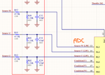
1.Analog method: through resistive voltage divider +LPF+ ADC( MCU input);
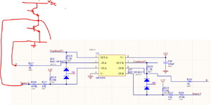
2.Digital method: opamp (non-inverting) + Digital MCU input;
the inverter is two-level, so we have a pwm type waveform.
My question is that what is the application of those measurements? Does anyone have similar experience?
this Drive uses single shunt current sensing method + Hall position sensor for closed loop
the circuit schematics for both methods are attached.
1.Analog method: through resistive voltage divider +LPF+ ADC( MCU input);
2.Digital method: opamp (non-inverting) + Digital MCU input;
the inverter is two-level, so we have a pwm type waveform.
My question is that what is the application of those measurements? Does anyone have similar experience?
this Drive uses single shunt current sensing method + Hall position sensor for closed loop
the circuit schematics for both methods are attached.