am85
Member level 2

- Joined
- May 30, 2011
- Messages
- 46
- Helped
- 1
- Reputation
- 2
- Reaction score
- 1
- Trophy points
- 1,288
- Location
- Germany
- Activity points
- 1,661
Hi,
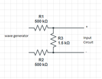
I am reading a high voltage square wave using an ADC. Firstly, I have a voltage divider using a 500k ohm resistor on every line coming from the wave generator and a 1.5k ohm resistor between both lines. Then comes the programmable amplifier and the ADC. I get the following plot :

Is this the correct signal i should get? If yes then why is the upper part of the wave a bit tilted and not straight anymore? and is it ok that the edges are round now? how to reduce those effects?
when I exchange the inputs to my circuit I get the following plot, which plot is the correct one ?

Thanks a lot in advance.
I am reading a high voltage square wave using an ADC. Firstly, I have a voltage divider using a 500k ohm resistor on every line coming from the wave generator and a 1.5k ohm resistor between both lines. Then comes the programmable amplifier and the ADC. I get the following plot :

Is this the correct signal i should get? If yes then why is the upper part of the wave a bit tilted and not straight anymore? and is it ok that the edges are round now? how to reduce those effects?
when I exchange the inputs to my circuit I get the following plot, which plot is the correct one ?

Thanks a lot in advance.


