Continue to Site

Welcome to EDAboard.com

Welcome to our site! EDAboard.com is an international Electronics Discussion Forum focused on EDA software, circuits, schematics, books, theory, papers, asic, pld, 8051, DSP, Network, RF, Analog Design, PCB, Service Manuals... and a whole lot more! To participate you need to register. Registration is free. Click here to register now.

Voltage divider for a square wave

Status
Not open for further replies.

am85

Member level 2
Joined
May 30, 2011
Messages
46
Helped
1
Reputation
2
Reaction score
1
Trophy points
1,288
Location
Germany
Activity points
1,661
Hi,

I am reading a high voltage square wave using an ADC. Firstly, I have a voltage divider using a 500k ohm resistor on every line coming from the wave generator and a 1.5k ohm resistor between both lines. Then comes the programmable amplifier and the ADC. I get the following plot :
500k_1.5k.png
Is this the correct signal i should get? If yes then why is the upper part of the wave a bit tilted and not straight anymore? and is it ok that the edges are round now? how to reduce those effects?
when I exchange the inputs to my circuit I get the following plot, which plot is the correct one ?
16k_47ohm.png

Thanks a lot in advance.
 

Your waveforms look exactly like those when an oscilloscope probe's compensating capacitor is not set to the "correct" value.

Here's a brief writeup on this --
https://www.ni.com/white-paper/4721/en

Without actually knowing your circuit setup, I suggest you connect in some small trimmer caps on your inputs, and adjust these for flat waveshapes - assuming your siggen is giving out a true square shape.

cheers!
 

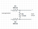
Yes I have read about this compensation capacitors. One source suggested having capacitors in parallel to every resistor of the voltage divider, but it didn't work. So can u please explain a bit more where exactly i should connect these capacitors. I have the voltage divider built in the cable between the wave generator and my circuit. then my input circuit looks like this:
design.png

My voltage divider in the cable looks like this:

voltage_divider.png

Thanks.
 

Yes I have read about this compensation capacitors. One source suggested having capacitors in parallel to every resistor of the voltage divider, but it didn't work. So can u please explain a bit more where exactly i should connect these capacitors. I have the voltage divider built in the cable between the wave generator and my circuit. then my input circuit looks like this:
View attachment 84384

My voltage divider in the cable looks like this:

View attachment 84385

Thanks.

i doubt i will be able to tell you EXACTLY where to put in caps, since this depends on a detailed knowledge of your entire physical setup. Randomly putting in caps everywhere doesn't sound a very useful idea - you'd be just shooting in the dark & hoping that BY SOME CHANCE you hit the right combination. I don't think so.

However if you Google for "oscilloscope probe compensating cap" or similar, you will get a host of details on real theory & practise.

Here's just a few that i found
**broken link removed**
https://www.picotech.com/applications/how-to-tune-x10-oscilloscope-probes.html
**broken link removed**

If you go through a few of these & understand the theory, then with a little thought you should be able to solve YOUR specific problem.

cheers1
 

Status
Not open for further replies.

Part and Inventory Search

Welcome to EDABoard.com

Sponsor

Back
Top